Author: Fersisolar Ingeniería y consultoría

Is it possible to clean receiver tubes with contact? Yes, if you know how!

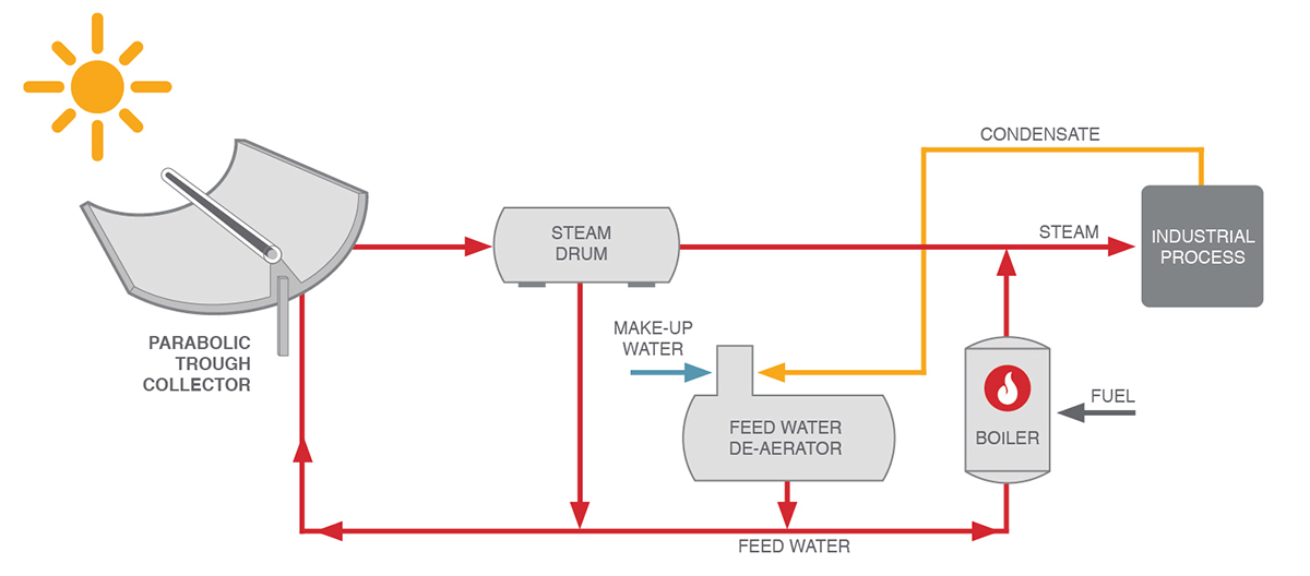
Concentrated solar power plants (CSP) use high amounts of direct beam irradiation to efficiently produce heat (and electricity, after that heat is fed into a turbine). Parabolic trough collectors (Figure 1) are a highly popular CSP technology and a type of concentrated solar collectors that use receiving mirrors curved in a parabolic shape along their longitudinal axis. These mirrors concentrate solar radiation onto the focal line of the parabola, where the receiver tube is located. Said tube contains the fluid we are heating up to nearly 400ºC, enabling high-temperature solar heat. The entire collection of reflectors and receivers is installed on a metal frame that tracks the sun’s movement throughout the day.

Overall, concentrated solar power (CSP) is a mature technology with several gigawatts of installed capacity worldwide. Still, a major challenge it faces lies in maintaining the optical efficiency of the system despite the persistence accumulation of soiling on the receivers and the reflecting mirrors. In fact, it is estimated that cleaning alone accounts for between 1% and 3% of net revenues in parabolic trough CSP plants[1]. In the next paragraphs we’ll discuss the issue in more detail and will introduce a novel solution.
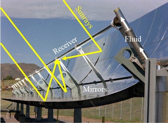


Figure 1: Operating principle of a parabolic trough collector

Soiling in parabolic trough solar thermal plants

Dust particles, pollen, industry emissions and others – jointly referred to as soiling – can incur losses of 3-4% even in plants with rigorous cleaning strategies[2]. The reasons behind this are manyfold[3]:

  1. Most evidently soiling blocks and absorbs part of the incoming radiation. Soiling on the reflectors reduces the amount of energy transferred over to the receivers; soiling on the receivers reduces the amount of energy passed on to the heat transfer fluid.
  2. Besides that, it increases the reflectance of the receiver – a piece engineered precisely with the goal of absorbing all the light concentrated on it – further driving losses. Radiation reflected back to the air is energy that cannot be captured by the heat transfer fluid.
  3. Lastly, soiling scatters part of the light reflected by the mirrors away from the receiver. The receiver is already a small target onto which to concentrate light. Thus, even a small deviation of a few milliradians in the path of the reflected beam of light can cause this energy to be sent away from the receiver and be lost. Yet the receiver is designed to be small out of necessity. Making it larger would mean increasing the diameter of the tube and a tube with a larger diameter has both higher material costs and higher energy losses due to a larger surface area.

Considering all the above – energy being blocked, reflected and scattered – CSP plants invest heavily in maintaining a high cleaning factor in their solar fields by cleaning the two key components of their parabolic troughs – the reflecting mirrors and the receivers. Maintaining these components is part of the optimization of solar thermal projects.

Cleaning component 1: reflecting mirrors

There are two ways to clean the reflecting mirrors – an in-contact brush that scrubs the collector and dislodges the soiling stuck on the surface and a water spray that pushes away loosely deposited particles. The two methods are seen as complementary and are applied together, as can be appreciated in Figure 2 below.
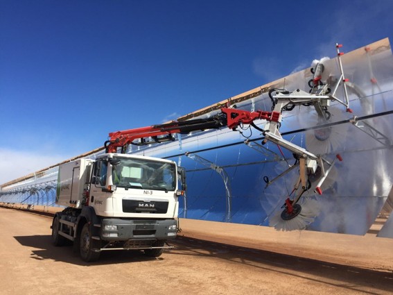


Figure 2: A specialised truck cleaning a parabolic trough with brush and water spray

Dust and soiling adhere to mirror surfaces through different mechanisms depending on the time it has spent deposed, environmental conditions, and particle composition. Over time, loose dust undergoes dynamic migration and stacking influenced by environmental factors, gradually transforming into more strongly adhered dust. This is why the two cleaning methods work best together – the water spray removes the loosely deposited material while the brush handles the strongly bound particles.

Still, cleaning using the spray method alone is faster because it bypasses the time-intensive mechanical contact process – more on the reasons why cleaning with a brush is slower in the next paragraph. This speed advantage is useful for more frequent, intermediate cleaning cycles that target only loosely deposited particles, which constitute the majority of recent soiling accumulation. Such cycles are carried out between the mixed brush-spray runs, or when the entire solar field requires rapid cleaning, such as after dust storms or seasonal soiling events.

In terms of risk of damage, the reflectors are robust enough to withstand the friction of brush contact when the brush is operated correctly. The brush systems are specifically designed with soft brush materials and water supply integration to minimize any potential surface damage while maintaining effective particle removal. Still, the process requires precise brush positioning, rotation synchronization, and careful contact management to prevent potential scratching of the mirror. Contactless spray cleaning, conversely, does not face this limitation. The mirrors are practically invulnerable to water spray jets, as pressurized water – while effective at particle removal – poses no mechanical damage risk to the reflective surfaces.

Cleaning component 2: receivers

The receivers, on the other hand, are a different story. Bot the inner and the outer side of the glass tube are covered in an anti-reflective coating. This is a thin, delicate film made of porous material, usually silicon dioxide[4]. The pores create destructive interference which greatly reduces the amount of light reflected from the surface of the glass tube and enhances the transmittance by up to four percentage points[5].

However, the silicon dioxide particles exhibit low binding force in between each other, requiring special care in the cleaning. Contact cleaning has been observed to cause scratching of the glass tube, reducing its mechanical strength, and peeling off of the coating layer[6]. Thus, contact cleaning is explicitly discouraged by receiver manufacturers, and but limits are placed on parameters when spray-cleaning, like water pressure, nozzle diameter and distance between nozzle and receiver.

However, spray-cleaning allows sticky soiling particles to embed in the porous structure of the anti-reflective coating and accumulate over the receiver’s lifetime. This issue is compounded by the fact that at present we are still lacking reliable measurement methodologies for the soiling of the receivers[7]. The net effect is that plant operators are aware of the progressively decreasing performance of their receivers, but are unable to quantify by how much, and in the absence of superior cleaning options, to take any action.

FersiSolar’s in-contact approach for receiver cleaning

In response to this persistent setback in the performance of the solar fields of our clients, FersiSolar has pioneered a new cleaning in-contact method for high-performance solar thermal equipment. This reliable solution gently removes sticky soiling without causing damage to the receivers. The approach is highly effective; when recently tested at a client’s plant, it delivered improvements of 6-7% in the plant’s performance. When asked for a comment, the engineering manager who supervised the tests said:

“It is impressive to see how quickly the plant performance metrics responded to the new cleaning method. We saw a clear and immediate jump in the output of the cleaned sectors. I understand that many colleagues would be apprehensive to start cleaning their receivers in-contact, after all nobody wants to damage their receivers. However, the method of FersiSolar is safe and as long as the operators who do the cleaning are attentive and careful, there is no reason to be worried.”

We look forward to expanding the implementation of this novel receiver on-contact cleaning process in concentrated solar thermal energy plants. Overcoming this roadblock in solar receiver soiling management is an important milestone in the competitiveness of this renewable technology. Would you like to know more? Contact us, we’re happy to share.

[1] https://doi.org/10.1115/1.4039631

[2] https://doi.org/10.1016/j.joule.2019.08.019

[3] https://www.solarpaces.org/wp-content/uploads/Document-3_SolarPACES_Soiling-Guideline_V0.1.pdf

[4] https://doi.org/10.1063/5.0028751

[5] https://doi.org/10.1016/j.egypro.2015.03.104

[6] https://doi.org/10.1016/j.egypro.2015.03.104

[7] https://doi.org/10.1016/j.applthermaleng.2026.131546

Sensible Thermal Energy Storage for Industry

Types of Sensible Thermal Energy Storage for Industry: Which One Fits Your Facility?

1. What Are We Talking About (and What Is Outside the Scope)?

Thermal Energy Storage (TES) is becoming an increasingly common component of solar thermal energy systems for industry. By making it possible to store heat generated during periods of high solar irradiation and use it when needed, TES helps reduce dependence on fossil fuels, increase the utilization of the solar field, and provide a more stable energy supply.

However, “energy storage” is a very broad term. In this article, we will focus exclusively on thermal energy storage, i.e., systems that store heat for use in industrial processes.

There are three main types of Thermal Energy Storage (TES): Sensible Heat Storage (SHS), which stores energy by increasing the temperature of the storage medium and is the type addressed in this article; Latent Heat Storage (LHS), which harnesses the energy associated with a phase change of the material, typically from solid to liquid, using a Phase Change Material (PCM); and Thermochemical Energy Storage (TCES), in which energy is stored through a reversible chemical reaction.

We will not cover electrical energy storage using batteries (BESS) or other applications, such as district heating networks or systems intended for buildings.

We will also limit the scope to the storage technologies most relevant to concentrated solar thermal (CST/SHIP) industrial installations, particularly those integrated with parabolic trough and Fresnel collectors. Other configurations and applications exist within thermal energy storage, but they address different temperature ranges, levels of technological maturity, or integration requirements.

The aim is not to analyze each technology in depth, but to help understand the factors that influence their selection. At the end of the article, you will find a comparative table summarizing the main characteristics of each option to facilitate an initial selection. If you want to explore a specific technology in greater depth, you will find links to other articles where we discuss it in more detail.

2. Why Incorporate Thermal Energy Storage (TES)?

Solar thermal energy makes it possible to replace part of fossil fuel consumption with a renewable energy source with no direct emissions during operation. However, solar resource availability does not always coincide with industrial process demand. In many facilities, thermal demand continues in the evening, at night, or during periods of lower irradiation, when the solar field can no longer supply all the energy required.

By storing heat produced during periods of high irradiation and releasing it later, TES makes it possible to shift energy over time and increase the utilization of the solar field. Instead of limiting the use of solar energy to daylight hours, the process can use that heat when it actually needs it.

A properly sized storage system can reduce conventional fuel consumption, increase the solar fraction of the plant, provide a more stable energy supply, and facilitate the operation of continuous industrial processes or processes with demand outside irradiation hours.

Incorporating storage is not simply a matter of adding more capacity. The technology selected, its size, and its integration with the industrial process all affect both the technical performance and the economic viability of the investment. Two facilities with similar total thermal demand may require very different solutions depending on their operating temperature, consumption profile, available space, or decarbonization strategy.

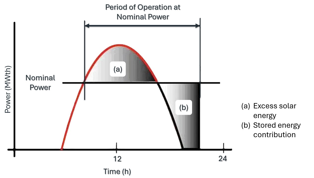
Figure 1. Example of (a) excess solar energy and (b) stored energy contribution over the course of a day.

3. There Is No One-Size-Fits-All Technology

Before comparing technologies, it is important to understand that there is no industrial thermal energy storage system that is the best option for every project – it depends on the specifications of each facility.

Process temperature is usually the first selection criterion, as it determines which materials and configurations can be used. However, it is rarely the only one. Other factors include the required storage hours, thermal demand profile, available space, integration with the existing facility, operating strategy, maintenance requirements, temperature difference between charging and discharging, efficiency, and budget.

In addition, different technologies have different levels of commercial maturity. Some have been used in industrial applications for several decades, while others are still evolving and offer promising characteristics, although with less widespread deployment.

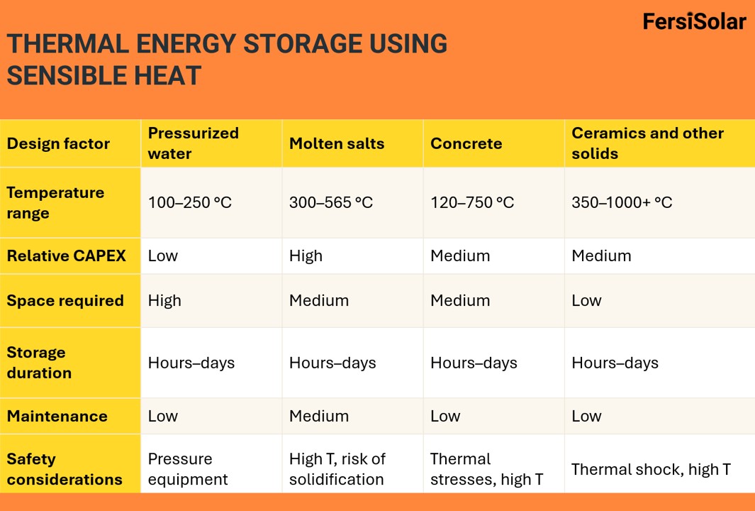
The following table summarizes the main thermal energy storage technologies used in low-, medium-, and high-temperature industrial heat applications and compares the factors that typically determine their selection.

4. Comparative Table of TES Technologies

Table 1 summarizes the main industrial thermal energy storage technologies currently used in industrial applications where steam or heat could be supplied through concentrated solar thermal (CST) energy. Its purpose is to provide a quick comparison of the factors that typically influence their selection.

The comparison focuses on the technologies with the greatest commercial deployment in this type of project. The values are indicative and should be interpreted as a guide for an initial assessment.

Table 1. Comparison of Thermal Energy Storage (TES) Technologies for Industrial Applications

5. How to Interpret the Table

The table makes it possible to quickly identify which technologies are worth considering and which are unlikely to be suitable for a given industrial thermal energy storage application. It does not replace engineering design, but it does help narrow down the alternatives from the outset.

It is common for one technology to stand out because of its suitability for a particular temperature range, another because of its relatively low cost or level of maturity and commercialization, and another because of its ease of integration.

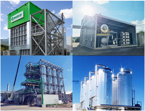
Figure 2. Four types of sensible heat storage. From left to right: (a) Magaldi Green Thermal Energy Storage based on fluidized sand-bed technology; (b) ENERGYNEST ThermalBattery™ concrete-based thermal energy storage; (c) Kyoto Group Heatcube using molten salts; (d) pressurized water thermal energy storage.

If you want to explore any of these technologies or topics in greater depth, you can consult our articles on Industrial Thermal Energy Storage – Part I, Industrial Thermal Energy Storage – Part II, Ceramic Thermal Energy Storage, and Nighttime Solar Electricity: Hybrid CSP Plants with Thermal Storage.

Conclusion

Thermal energy storage can increase the utilization of solar energy and provide greater flexibility to an industrial facility, contributing to the decarbonization of industrial heat. The most suitable technology will depend on factors such as process temperature, demand profile, available space, and integration with the solar field.

The table presented in this article is intended to serve as an initial reference for comparing the main alternatives and identifying which ones are worth considering for each project.

At FersiSolar, we help industrial companies design and integrate thermal energy storage systems for new installations and existing concentrated solar thermal plants. If you are considering incorporating TES into your process, we can help you assess the different alternatives and select the solution that best fits your facility and objectives.

Energy Saving Certificates (CAEs) in Spain: An Economic Driver for Industrial Decarbonization

Why Talk About CAEs Now?

The energy sector is entering an important deployment phase. Energy efficiency and fossil fuel reduction technologies are being applied in industrial environments with measurable results. The next step is to facilitate the implementation of these projects.

Energy Saving Certificates (CAEs) introduce an additional variable into decision-making by assigning a direct economic value to the savings generated. Energy savings are reflected in a reduction in consumption and an associated additional income. This changes the investment analysis, expands the number of viable measures, and improves their profitability.

CAEs are a tool for financing the implementation of industrial projects. This article presents the fundamentals of the system, its application to industrial projects, and FersiSolar’s role in integrating this type of solution.

What Are CAEs?

CAEs represent certified final energy savings, measured in kWh, generated by a specific action. The difference between an initial and a subsequent situation is quantified through Royal Decree 36/2023, verified through the instructions of the assigned standardized measure, and converted into an asset within the system.

One example of the application of CAEs is the transition from natural gas boilers to high-efficiency electric boilers at an industrial plant. This action significantly reduces natural gas consumption and the associated CO₂ emissions. By generating energy savings, the plant can obtain CAEs, which are tradable on the market, thereby providing an additional source of income and promoting economic sustainability. In this way, not only does the project contribute to industrial decarbonization, but it also promotes a responsible commitment to the environment.

The process involves technical validation of the savings through validated calculation methodologies and correction factors, as well as independent verification by an accredited entity. It is subsequently processed through authorized agents and issued by the regional administration, with registration at national level.

Once issued, CAEs can be traded. Energy savings therefore acquire economic value in addition to reducing consumption. This link between technical savings and economic value is what makes the mechanism relevant for industrial projects.

Important clarification: The system measures energy savings, not emissions, although both effects are usually aligned.

Generating Value from Energy Savings

The CAE system is based on a regulatory obligation: energy retailers and suppliers must meet annual energy-saving targets (obligated parties). To do so, they can contribute to the FNEE (National Energy Efficiency Fund) or acquire CAEs generated by projects.

This connects the different stakeholders: a company reduces its consumption, those savings are certified, and they become an asset that other parties need to acquire.

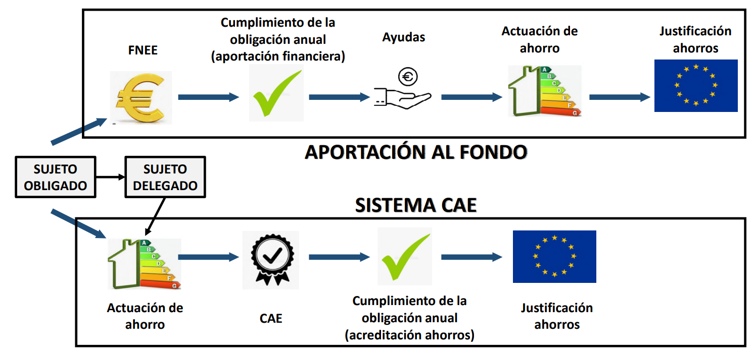
The mechanism follows a simple flow: savings → certification → transfer of value to the project, as shown in Figure 1.

Figure 1. The CAE vs. FNEE process. Source: MITECO

France as a Reference

This approach is already established in reference markets such as France. France has had the CEE (Energy Efficiency Certificates) system since 2005, fully integrated into its energy market. Its adoption in Spain makes it possible to assign value to energy savings within a similarly structured framework.

The system includes standardized measures that simplify implementation and reduce the administrative burden. This facilitates validation and adoption across different sectors. The revenues associated with savings are incorporated into projects from the outset, together with investment and energy savings.

Spain is adopting a model supported by this experience, accelerating its implementation curve.

Spain: Current Status

The CAE system was introduced in 2023 and is currently being deployed. The number of projects is growing and standardized measures are being developed.

Currently, many projects are assessed on a case-by-case basis, particularly in complex industrial environments. In concentrated solar thermal applications, there is still no standardized measure, although proposals are under evaluation.

However, projects can be developed as specific actions, allowing savings to be certified through specific verification. This makes it possible to monetize savings today while the system evolves towards greater standardization.

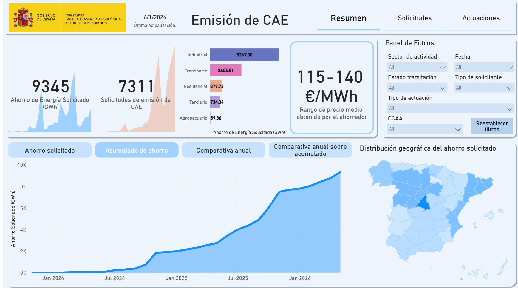
According to Figure 2, approximately 7,311 applications for CAE issuance have been submitted up to 2026, representing total energy savings of 9,345 GWh, of which industry accounts for more than 50%.

Figure 2. Current status of CAE issuance.

The Role of Industrial Heat and Concentrated Solar Thermal Technology

Heat accounts for a significant share of industrial energy consumption, particularly in steam processes and medium- and high-temperature applications. Replacing fossil fuels with concentrated solar thermal technologies makes it possible to directly reduce this consumption. This reduction can be quantified and fits within the CAE system.

This type of action is eligible provided that it results in a reduction in final energy consumption at the facility.

Practical Example: Integration in the Food Industry

To understand how the generation of CAEs can influence the economics of an industrial plant, such as a brewery, dairy facility, or food processing plant, a simplified example is presented below.

Figure 3. Integration of concentrated solar thermal energy into industrial processes. Source: IDEA, 2025.

This example can be approximately represented as shown in Figure 3. The plant has a high thermal demand for steam in processes such as cooking or cleaning.

Initial Situation

  • Thermal consumption: ~40 GWh/year
  • Steam supplied by a gas boiler (~10 MWt)
  • The concentrated solar thermal system is integrated into the existing circuit, displacing gas consumption during solar hours, while the boiler acts as backup.

Intervention

  • Concentrated solar thermal (~5 MWt)
  • Integration with the existing system
  • Thermal energy storage
  • With ~5 MWt, approximately 25% of annual demand is covered, reducing gas consumption by ~10,000 MWh.

Result

  • Solar production: ~10 GWh/year
  • Gas reduction: ~25%
  • Energy savings: ~10,000 MWh/year

These savings can be certified as CAEs, subject to the baseline, operating conditions, and verification.

CAEs Generated

  • ~10,000 CAEs

The associated income is incorporated into the project’s economic model, improving its viability.

Economic Value

  • Indicative market price: ~€115–140/MWh
  • Revenue: €1.15–1.40 million

How FersiSolar Fits In

FersiSolar designs and integrates concentrated solar thermal systems adapted to industrial processes, including generation, integration, and storage. The result is a measurable reduction in fossil fuel consumption that may be eligible for certification as CAEs.

In addition, project preparation from the outset includes defining the baseline, identifying savings, and structuring the project for verification in accordance with the guidelines of Royal Decree 36/2023.

This approach not only contributes to industrial decarbonization, but also improves the company’s economic sustainability by diversifying its sources of income and reducing operating costs in the long term.

The Current Market Reality

Energy efficiency solutions are already deployed in industry and operate under real service conditions. Projects combine investment, operation, and energy savings, increasingly incorporating revenues associated with CAEs. The CAE system adds a mechanism that connects these savings with the market and allows them to be assigned economic value.

Its development is progressing, with verification and standardization processes gradually maturing, particularly in complex industrial applications. This makes it possible to structure projects more robustly as the system evolves.

At FersiSolar, we firmly believe that what is good for the planet can also be good for business. We are excited to see environmental improvements becoming increasingly profitable.

Leading Heat Collection Element Decisions in CSP Plants

HCE Supply for CSP Plants

Over the past year, FersiSolar structured and executed its first Huiyin Receivers (HCEs) supply project for a CSP plant. That first operation marked the beginning of a line of work that has since been consolidated through new technical assessments, economic analyses, and discussions with operators facing similar challenges in their plants and solar fields.

This work is supported by solid experience in CSP technologies and a deep understanding of how these facilities operate as a whole. From solar field design to the day-to-day operation of the CSP plant, we provide technical judgment based on an integrated view of the asset, understanding that the performance and profitability of a facility are determined by the interaction between technologies, operating conditions, and economic objectives. This system-level perspective is the foundation from which we guide decision-making in projects.

Heat Collection Elements (HCEs), or receivers, play a key role within the solar field, as they are responsible for transforming concentrated solar energy into useful thermal energy. Their performance directly affects thermal losses, solar field efficiency, and the plant’s annual output.

The HCE as Part of the System

Thanks to our global technical knowledge of CSP technologies, we assess and structure decisions regarding receivers (HCEs), considering their interaction with the existing design, operating temperatures, thermal ramp rates, and operation and maintenance requirements.

By analyzing these aspects, we define clear decision-making criteria, guiding our clients towards coherent and sustainable decisions aligned with the actual operation of the CSP plant and its technical and economic objectives.

In many cases, this approach makes it possible to identify additional technical and economic optimization opportunities, combining HCE selection with design or operational adjustments that amplify the benefit to the asset’s overall performance.

Why Huiyin Receivers (HCEs) Are a Preferred Option

Huiyin receivers (HCEs) have demonstrated a strong technical fit for the projects assessed within this line of HCE supply projects. They incorporate stable high-temperature selective coatings, advanced vacuum and hydrogen management, and unique in-line re-evacuation technology, which makes it possible to restore the tube’s thermal conditions without replacing it.

These characteristics provide operational flexibility, reduce the impact of degradation, and contribute to maintaining competitive solar heat for industry. From a technical and economic perspective, they stood out as the best solution within the evaluation process, aligning with actual operating conditions and showing clear potential to recover solar field performance.

For this reason, Huiyin receivers were positioned as the preferred option within the evaluation process and ultimately selected by the clients themselves as the optimal solution within the broader framework of a CSP plant optimization strategy.

Effective Lifetime and Degradation as Key Factors

Although HCEs are generally designed for a theoretical service life of several decades, plant experience shows that their effective lifetime is affected by progressive degradation. Vacuum loss, hydrogen accumulation, and coating aging progressively increase thermal losses.

At FersiSolar, we systematically analyze CSP plant performance, interpreting how this degradation evolves and how it translates into technical and economic impacts. This approach makes it possible to determine when an intervention – such as HCE replacement – provides a tangible benefit in terms of cost, performance, and system reliability.

Evaluating HCE Replacement or Performance Improvement

In most CSP plants, the need to assess HCE replacement arises from actual operating conditions. The first signs are often subtle: deviations in output, progressively increasing thermal losses, or reduced stability in operating temperatures.

At this point, we define the optimal timing for intervention together with the operator, identifying when to act to recover performance, improve energy efficiency, and protect asset value. This analysis considers the impact on renewable heat production, operating costs, and project objectives.

Long-Term Operational Capability

Beyond technology selection, the projects we structure focus on strengthening the long-term operational capabilities of plants. This includes technical support during the integration of new solutions, knowledge transfer, and clarity in the analytical criteria used.

The result is a CSP plant with improved thermal balance, greater operational control, and clearer visibility into its performance. At the same time, the asset is better prepared to sustain and expand these improvements over time, integrating optimization into a strategy aligned with the energy transition in industry.

About FersiSolar

FersiSolar was founded on the extensive international experience of its main founder, Toni Fersini, in the concentrated solar power sector. Its objective is to put this experience at the service of asset owners, investment funds, and financial institutions.

The company is built around three key pillars:

  • Advisory services for CSP plant operation and maintenance companies
  • Engineering and technical consulting for solar thermal energy solutions
  • Sustainable heat supply for industry

From this foundation, FersiSolar structures and guides complex decision-making in CSP plants, turning technical analysis into real and profitable improvements in performance, energy efficiency, and emissions reduction.

Let’s Collaborate

Decisions related to HCE replacement, performance improvement, or solar field optimization require a comprehensive view. They require an understanding of how technologies interact and how the system evolves over time.

If a CSP plant or project is evaluating these options in the context of renewable industrial heat and decarbonization, FersiSolar can support and guide the decision-making process, providing technical judgment, practical experience, and a results-oriented perspective.

Another Starling Reference for FersiSolar

Following the successful completion of yet another project, FersiSolar once again demonstrates what consistent solar field expertise looks like when applied to real operating conditions – translated into delivered results. 

Project Context and Scope of Services 

The project addressed a familiar but critical challenge in large solar thermal plants: the gap between expected performance under theoretical design conditions and actual performance under realworld operation. While the plant was engineered to meet specific output and efficiency targets, observed behavior over time revealed deviations driven by operational constraintscomponent performance variability, and systemlevel interactions within the solar field. 

To address these challenges, FersiSolar was engaged to deliver a comprehensive and integrated set of services, including: 

  • Advanced plant and solar field performance analysis based on operational data 
  • Root Cause Analysis (RCA) of lowperforming collectors, using tracking, optical, and thermal performance assessment 
  • Continuous remote monitoring of solar field performance, including early detection of abnormal behavior and timely notification protocols 
  • Targeted recommendations to improve temperature controlflow management, and solar field balancing 
  • Multidisciplinary solar field engineering support across mechanical, process, I&C, electrical, and civil disciplines 
  • Onsite engineering support during construction activities and throughout commissioning 

These services were delivered as a single, coordinated effort, ensuring technical consistency from diagnosis through implementation and enabling the plant to progressively close the gap between theoretical expectations and achieved operational performance. 

From the outset, the collaboration focused on establishing a clear, data‑driven understanding of plant behavior and operational constraints under real conditions. The engagement was addressed as a cohesive, end‑to‑end effort, integrating analysis, operational support, and on‑site engineering activities. 

The strength of this foundation was clearly recognized by the customer: 

“FersiSolar demonstrated strong expertise in optimizing plant operation, identifying concrete performance improvement opportunities through detailed plant data analysis.” 

This analytical depth formed the backbone of all activities delivered throughout the project. 

Identifying the Real Sources of Underperformance 

A key pillar of the project was the precise identification of performance limitations within the solar field. A structured diagnostic process was applied to investigate performance deviations at collector level, supported by detailed operational data and field measurements. 

Rather than focusing on isolated symptoms, this structured approach enabled a clear understanding of underlying causes, interactions between subsystems, and recurring patterns affecting performance. As a result, corrective actions could be prioritized based on impact and operational relevance, rather than applied generically across the field. 

The customer emphasized the value of this approach, noting that:

“FersiSolar showed deep experience in the Root Cause Analysis of lowperformance collectors by combining tracking data with optical and thermal performance assessment, enabling rapid identification of underperforming collectors and timely, effective corrective actions.” 

This methodology allowed inefficiencies to be isolated with accuracy, ensuring responses were targetedactionable, and firmly grounded in measurable plant data, with a direct impact on longterm emissions reduction and performance stability. 

Driving Measurable Solar Field Performance Improvements 

Building on this analytical foundation, FersiSolar delivered clear and actionable recommendations aimed at improving overall solar field performance. Particular attention was given to critical operational parameters such as temperature control and solar field balancing, ensuring stable operation and optimized energy delivery to the power block. 

These recommendations were developed with a strong operational mindset, aligning detailed engineering insight with practical, daytoday plant implementation. Emphasis was placed not only on achievable performance gains, but also on ensuring that proposed actions could be sustained under variable operating conditions and evolving plant constraints. 

 Continuous Oversight Through Remote Monitoring 

To safeguard performance gains and support operational stability, routine support was delivered through continuous remote monitoring of the plant’s performance. 

Remote monitoring was used as a permanent operational support tool, providing continuous visibility of solar field behavior over time. This approach supported early detection of deviations, reduced response times, and enabled informed operational decision‑making during transient conditions, maintenance periods, and off‑design operation. 

The importance of this capability was clearly acknowledged by the customer, who described that:

“The service provided by FersiSolar includes routine support through remote monitoring of the plant’s performance, with immediate notification protocols for any abnormal behavior detected within the solar field.” 

Comprehensive Solar Field Engineering Support 

The project also involved extensive solar field engineering support across mechanical, process, I&C, electrical, and civil disciplines. This included advanced analysis of the existing solar field and its hydraulic limitations, ensuring systemwide impacts were fully understood prior to implementation. 

In parallel, FersiSolar supported onsite inspections during construction activities and provided technical assistance throughout commissioning, maintaining alignment between design intent, installation quality, and operational readiness. The breadth of activities was handled as a unified scope, strengthening overall industrial competitiveness. 

A Structured, LongTerm Technical Partnership 

This project collaboration was not limited to isolated studies or oneoff interventions, but rather evolved into a structured, ongoing technical engagement extending over operational periods. Analysis, monitoring, and engineering support were applied iteratively, allowing findings from one phase to be validated, refined, and extended in subsequent operating windows. 

Throughout the engagement, FersiSolar worked seamlessly across borders, cultures, and project teams, integrating effectively with owners, operators, and onsite personnel to ensure clarity, alignment, and continuity. 

Reflecting on this collaboration, the customer stated: 

“FersiSolar’s experience and proactive approach make them a key partner in our operations, and we are confident in their ability to deliver substantial improvements in solar field performance.” 

Strengthening LongTerm Operational Capabilities 

Beyond immediate performance improvements, the project simultaneously placed strong emphasis on longterm operational robustness. Targeted onsite training and detailed written instructions were provided to support both current solar field strategies and future optimization opportunities. 

Plant personnel were trained with full transparency into calculations, methodologies, and engineering logic, reinforcing technical understanding and operational confidence across the team. 

Results That Extend Beyond the Project Scope 

The result of this collaboration was a solar field operating with improved balance, enhanced temperature control, and stronger performance visibility. Just as importantly, the plant emerged better equipped to sustain and build upon the improvements achieved. 

This project stands as another strong reference for FersiSolar’s role as a trusted engineering and consulting partner for parabolic trough CSP plants worldwide. With experience spanning engineering, construction, commissioning, and O&M optimization, FersiSolar consistently delivers expertise that translates into real operational value. 

To learn more about this specific project competency, or to explore how our services can support your unique solar field, get in contact with us. 


Eficiencia, Alianzas y el Camino a las Cero Emisiones: Nuestra llegada a ANESE

El sector energético está experimentando su mayor transformación. Conceptos que antes eran técnicos, como “descarbonización” o “servicios energéticos”, hoy están en el centro de las estrategias de cualquier empresa competitiva. Por eso, hemos dado un gran paso en la Asociación Nacional de Empresas de Servicios Energéticos (ANESE).

  1. ¿Qué son los Servicios Energéticos y cómo funcionan?

Para entender el valor de nuestra incorporación a ANESE, primero hay que entender el funcionamiento de las Empresas de Servicios Energéticos (ESE).

A diferencia de una consultora tradicional, el enfoque de una ESE no está en vender equipos sino en garantizar resultados de ahorro.

El funcionamiento del modelo ESE

Se basa en la mejora de la eficiencia energética en las instalaciones de un usuario, ofrecen un conjunto de servicios que incluyen la realización de inversiones inmateriales, obras o suministros para optimizar la calidad y reducir los costes energéticos.

  • Auditoría y Diagnóstico: Se analiza dónde se está perdiendo energía y que cambios tecnológicos son los más rentables.
  • Implementación de medidas: Se instalan soluciones tecnológicas avanzadas (fotovoltaica, aerotermia, sistemas de control inteligente).
  • Gestión del Riesgo: El cliente no asume el riesgo de que la tecnología no funcione; es la ESE quien garantiza que, si no hay ahorro, no hay beneficio.
  • Verificación y Medida: Se utilizan protocolos internacionales para demostrar, con datos reales, cuánto CO2 y cuánto dinero se está dejando de emitir y gastar.
  1. Nuestra incorporación a ANESE:

ANESE es la asociación de referencia en España que agrupa a las organizaciones y especialistas más relevantes del ámbito energético en España.

Nuestra entrada en este grupo no es un mero trámite, es una validación de nuestra forma de trabajar.

¿Qué supone para nosotros?

  • Certificados de Ahorro Energético (CAEs): Estamos integrados en el nuevo sistema que permite monetizar los ahorros de energía, devolviendo parte de la inversión a nuestros clientes de forma mucho más ágil que las subvenciones tradicionales.
  • Seguridad y transparencia: Trabajamos bajo estándares reconocidos que dan tranquilidad a nuestros clientes. Pertenecer al grupo de ANESE es una garantía de buenas prácticas.
  • Formación continua: Nos permite estar al día de los cambios constantes en la normativa energética, algo muy importante para poder asesorar de manera adecuada a cualquier empresa o institución.

No queremos ser una empresa más que pertenezca al grupo simplemente por aparecer en una lista, sino que queremos participar activamente en todos los proyectos que nos sea posible ya que a partir de todo el trabajo que se está llevando a cabo, se definirá como será gestionada la energía en la próxima década

  1. La Descarbonización:

Todo lo anteriormente comentado tiene un objetivo superior: la descarbonización.

España y la Unión Europea tienen metas legales muy estrictas para alcanzar la neutralidad climática en 2050. Sin embargo, la descarbonización es un proceso profundo que se basa en tres pilares donde nuestra labor es crítica:

  • La optimización del consumo como punto de partida

La energía más limpia es la que no se llega a consumir, antes de plantear cualquier cambio en la fuente de suministro o instalar generación renovable, es vital optimizar la demanda existente.

Reducir el consumo innecesario es la vía más rápida y rentable para la descarbonización, ya que disminuye las emisiones de forma inmediata mientras mejora la competitividad económica.

  • La implementación de fuentes renovables 

Descarbonizar implica sustituir procesos térmicos fósiles (calderas de gas o gasoil) por sistemas termosolares o eléctricos de alta eficiencia en función del caso. Al ser socios de ANESE, facilitamos que esta transición tecnológica sea económicamente viable para las empresas a través de ahorros compartidos.

  • El papel de los Certificados de Ahorro Energético (CAE)

Este es el gran aliado de la descarbonización actual, el sistema de CAEs incentiva que las empresas inviertan en eficiencia energética. Por cada kWh de energía que no ha sido consumido mediante una mejora tecnológica, se genera un certificado que tiene un valor económico. Esto acelera el retorno de inversión y hace que descarbonizar sea, por fin, un buen negocio.

En conclusión, nuestra incorporación a ANESE representa el compromiso de llevar la descarbonización del papel a la realidad.

Estamos convencidos de que el modelo de servicios energéticos es la herramienta más eficaz para que el tejido empresarial español cumpla sus objetivos climáticos sin perder competitividad.

HCEs degradation; observation from a power plant

We recently completed an exhaustive inspection and technical evaluation campaign at a Concentrating Solar Power (CSP) plant, specifically focusing on the Heat Collecting Elements (HCEs), or receivers. These components are, without a doubt, the core of the Parabolic Trough Collector (PTC) technology, and their performance defines the economic and operational efficiency of the entire power station. The evaluation, which covered various Solar Collector Assemblies (SCAs), allowed for the collection of a vast amount of operational and diagnostic data in the field.

The primary objective of this campaign was to compare the performance between HCEs supplied by different manufacturers, analyzing key variables such as physical condition, thermal stability, and, fundamentally, the critical metric that reflects the element’s vacuum status. The findings have been revealing.

Of all the components analyzed, the receivers (HCEs) from the manufacturer Hiuyin distinguished themselves by exhibiting the best overall performance. Their superiority was not coincidental; it manifested through excellent visual condition (minimal signs of corrosion or material degradation), but in their exceptional behavior regarding the normalization temperature metric and the resulting thermal efficiency.

The Essence of the HCE: Why Vacuum is Key

To understand the importance of the performance metric, it is essential to grasp the function of the HCE. An HCE consists of an inner absorber tube, through which the Heat Transfer Fluid (HTF) circulates, surrounded by an outer glass envelope. The annular space between the two tubes is evacuated to an extremely high vacuum level (typically in the range of 10-4 to 10-3 mbar).

This vacuum chamber plays a vital role: eliminating heat transfer by convection and conduction from the hot absorber tube to the ambient surroundings. Without the vacuum, the glass tube would act as a simple insulator, and the captured thermal energy would be rapidly lost to the atmosphere, drastically reducing the HTF temperature and, consequently, the power generated in the Rankine cycle (or any other power cycle).

In addition to the vacuum, the absorber tube is coated with a selective layer, designed to have high solar radiation absorption (α = 0.95) and low thermal emissivity (Ɛ = 0.10). The combination of the selective layer (which minimizes outgoing radiation) and the vacuum (which eliminates convection/conduction) is what allows the HCE to reach and maintain such high operational temperatures, often exceeding 350ºC.

The Evaluation Metric: A Direct Indicator of HCE Health

The performance metric referenced in the evaluation, which relates to “normalization temperature behavior” and vacuum status, is perhaps the most valuable and sensitive health indicator of an HCE. As mentioned, this metric is a measure of the Heat Loss from the absorber, normalized or compared under standardized operational conditions.

Key Variables:

  • Tamb,t is the ambient temperature in ºC in the minute the measurement was taken.
  • THTF,t is the HTF temperature in ºC in the minute the measurement was taken.
  • Tobserved,HCE,t is the average temperature in ºC of all observations for the particular HCE in the minute the measurement was taken.

Interpretation of the Metric: Vacuum Diagnosis

The final value of this metric is interpreted as follows:

  • Stable and Negative Values: These indicate a well-preserved vacuum condition ( < 0 or similar). This means the measured heat loss (represented by Tnormalized,HCE,t ) is below or very close to the optimal reference value (corresponding to a perfect vacuum).
  • Values Near Zero or Positive: These signal a significant loss of vacuum (≥ 0). When the vacuum degrades, the residual gas begins to conduct and convect heat out of the absorber, increasing the loss. This causes the measured value ( or the calculated ) to increase. The result is a notable reduction in efficiency and a lower HTF outlet temperature under the same irradiance.

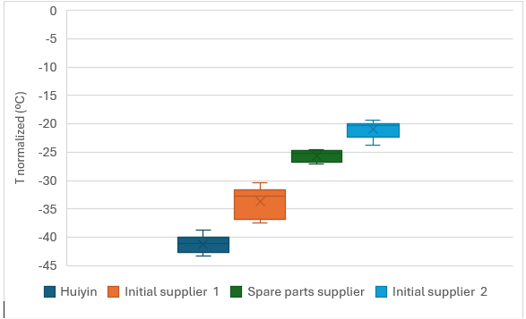
  • Considering that both were installed at the same time, the graph clearly shows that Huiyin receivers perform significantly better than those of other providers.
  • Looking at the previous graph, it’s clear that initial supplier 1 performs better than initial supplier 2. It’s surprising, considering they were both installed at the same time.

Re-evacuation.

As we can see, HCEs naturally deteriorate over time, since their internal vacuum gradually decreases and performance drops. However, even the Huiyin receivers offer a very valuable advantage: their re-evacuation capability.

This process makes it possible to restore the vacuum level almost to its original state, and it also allows the getters to be reused. The hydrogen they have accumulated can be removed again through a high-vacuum, high-temperature treatment, and Huiyin has the proper equipment to carry this out. Even better, a getter can be recycled up to about ten times.

This re-evacuation capability is highly beneficial because it allows us to extend the useful life of the HCEs for many more years, maintaining their performance and reducing the need for premature replacements.

  1. Warranty Validation and Supplier Evaluation

As demonstrated with Hiuyin’s HCEs, this normalized temperature  is fundamental for the comparative evaluation of suppliers. It allows owners and operators to:

  • Validate Manufacturing Quality: A supplier that consistently produces HCEs that maintain stable negative values for years demonstrates superior quality in materials, the glass-to-metal sealing process, and the final vacuum level. This translates into a lower Levelized Cost of Energy (LCOE) over the long term for the plant.
  • Enforce Warranty Clauses: Contractual HCE warranties are often tied to the maximum heat loss rate. If this normalized metric exceeds a predefined threshold within the warranty period, the operator has objective and  quantifiable proof to request free replacement from the manufacturer. Even in this field, Huiyin provides a distinct advantage, offering a warranty period that is considerably longer than those of other suppliers.
  1. Plant Performance Optimization

Vacuum loss in a single HCE can have a surprisingly disproportionate impact on the entire collector row. When one HCE fails, it starts taking heat away from the HTF flowing through it, and that drop in outlet temperature forces the control systems to make less efficient choices—sometimes concentrating sunlight more aggressively, other times reducing flow just to compensate. And honestly, none of that helps.

This metric ensures that the plant operates with as many collectors as possible under their optimal design conditions. When all HCEs maintain negative normalized loss values, the solar field efficiency stays at its peak. The outcome is clear and genuinely valuable: higher operating income and, just as importantly, greater clean energy generation.


Concentrated Solar Thermal Energy Guide

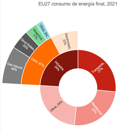
The decarbonization of industry represents one of the major challenges of the energy transition. Heat is at the heart of this challenge: two-thirds of annual energy consumption in industries in the European Union is used for process heat. At present, the vast majority of this consumption is supplied by fossil fuels, with natural gas playing a central role.

Figure 1: Final energy consumption in the EU in 2021. Source: World Energy Balance 2022, IEA

With the aim of promoting the deployment of technologies that can change this situation, the Institute for Energy Diversification and Saving (IDAE) has published the “Guide to Concentrated Solar Thermal Energy for Industrial Processes”. This document provides detailed and relevant information on concentrated solar thermal energy technology, particularly aimed at industrial users seeking sustainable and efficient alternatives for their medium- and high-temperature, energy-intensive processes (100–400°C). In this blog, we summarize the most important information from the Guide.

The Role of the Technology

Concentrated solar thermal (CST) energy is emerging as one of the most attractive solutions for meeting industrial thermal demand. It is a proven technology capable of supplying renewable heat in a stable and competitive way, integrating robustly into industrial processes through the use of thermal energy storage, ensuring operational continuity and reducing dependence on fossil fuels.

Sectors and Processes of Interest

CST is particularly well suited to industries requiring heat in the medium-temperature range (100–400°C).

  • In the food and beverage sector, for example, it can be integrated into processes such as drying, pasteurization, sterilization, and industrial frying.
  • In the chemical and plastics industries, CST can cover synthesis, distillation, extrusion, and polymer molding.
  • The textile sector, which is heat-intensive for dyeing, drying, and fabric finishing, can also find a realistic and scalable alternative in CST.
  • Mining and construction materials, with processes such as mineral drying and gypsum kilns, represent sectors with high thermal demand and available space for solar installations.

The industrial processes of greatest interest for CST include steam and hot water production, drying treatments, and separation processes. A key aspect is thermal energy storage, which makes CST a competitive option compared with alternatives such as photovoltaics, as it ensures thermal supply at night or during cloudy periods. This is particularly valuable for factories operating continuously or with stable thermal loads.

Other Technologies for Decarbonization

When comparing the different decarbonization options available for industrial processes in the 100–400°C range, the conclusion is clear. Biomass can provide heat, but it raises significant environmental concerns: it competes with biodiversity, generates air pollution, and also emits greenhouse gases in the present that must be reabsorbed through the growth of new forests in the future. Industrial heat pumps, meanwhile, although highly promising, still do not have commercial solutions capable of reaching these temperatures and currently supply heat only up to 150°C.

Electric boilers powered by self-consumption photovoltaics are the only real alternative to solar thermal with a competitive price, due to the low cost of photovoltaic modules and the possibility of participating in ancillary services markets for the electricity grid. However, solar thermal also has its advantages, foremost among them lower land requirements.

Against this backdrop, concentrated solar thermal energy offers a robust proposition: renewable, continuous heat, with a price that depends on the…

Institutional Recognition of the Technology

Thanks to these advantageous characteristics, institutional support for CST is growing significantly in Spain. Among the most important programs and initiatives are the following:

  • The Energy Saving Certificate (CAE) system, which allows the energy savings achieved through solar thermal installations to be monetized, generating an additional revenue stream that improves project profitability. A specific measure for the technology is expected to be published; it is currently under development.
  • The Recovery, Transformation and Resilience Plan includes specific funding for renewable heat projects in industry, with an emphasis on integrating solutions such as CST.
  • European Regional Development Fund (ERDF) funds for 2021–2027 also support renewable energy investments in regions with high potential, opening the door to scalable projects beyond the pilot phase.
  • The LIFE Programme, in turn, finances innovation and demonstration projects that are essential for validating novel applications in specific industrial sectors.

Alongside institutional support, the economic model has also evolved. The Heat as a Service (HaaS) model is emerging as a transformative element, as it removes the initial investment barrier for industrial customers. Under this model, the customer does not purchase the plant but pays only for the heat consumed. In this way, the technology and operational risk is assumed by the service provider, while the beneficiary company obtains renewable heat at stable and predictable prices. This approach is particularly attractive in a context of high gas and electricity price volatility, as it provides economic certainty and competitiveness. It also allows small and medium-sized industries, which under other circumstances might not be able to afford an investment in CST, to access the benefits of the technology.

Conclusion

In conclusion, decarbonizing industrial heat in the 100–400°C range is an important challenge in the energy transition. The options are limited: biomass, with its environmental impacts; electrification through electric boilers, which are competitive but dependent on electricity prices and more land-intensive due to the photovoltaic generation required; and, finally, concentrated solar thermal energy. Among these options, CST stands out as the most mature, competitive, and scalable. It provides renewable and continuous heat thanks to thermal storage, can be adapted to multiple industrial sectors, benefits from growing institutional support, and offers innovative business models such as Heat as a Service, which reduce barriers to entry and facilitate widespread adoption.

Spain, with its exceptional solar resource and supportive institutional framework, has the opportunity to position itself at the forefront of this transformation and lead the decarbonization of industrial heat in Europe.

Guided visit to Andasol 3

Over the last weekend, FersiSolar joined the program of the annual conference of SolarPACES, the leading technology collaboration programme of the International Energy Agency (IEA) on concentrated solar power technology (CSP). In this year’s edition, the conference included a tour of the Andasol 3 solar thermal power plant, which is operated by Marquesado Solar. As the team of FersiSolar participated in the construction of Andasol 3, we were more than happy to give a helping hand with the organization of the tour.

It was an amazing experience to have insightful conversations with the attendees and engage with their questions about the design of the plant. With such strong backing by dedicated and motivated researchers, we are certain that concentrated solar thermal energy has a long and fruitful way ahead. Continuing the energy transition, especially in the decarbonization of industrial heat consumption, is not a small challenge, but the research community is up to the task. Furthermore, it was very encouraging to see that Marquesado Solar has done an excellent job in maintaining Andasol 3 in peak condition even after more than a decade of operation.

The tour

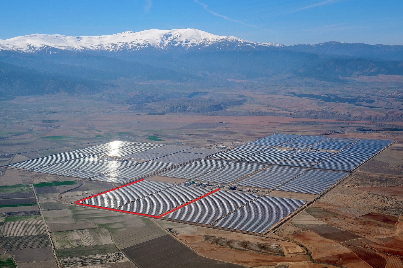
Picture 1: Andasol 3 in the foreground with a red rectangle of the visited sector, Andasol 2 to its left and Andasol 1 in the background

The tour started with a drive around the block circled in red above. Toni Fersini, the CEO of FersiSolar and the engineering director of the construction of the solar field, joined the attendees of the conference and touched on some of the intricacies of how such a field works.

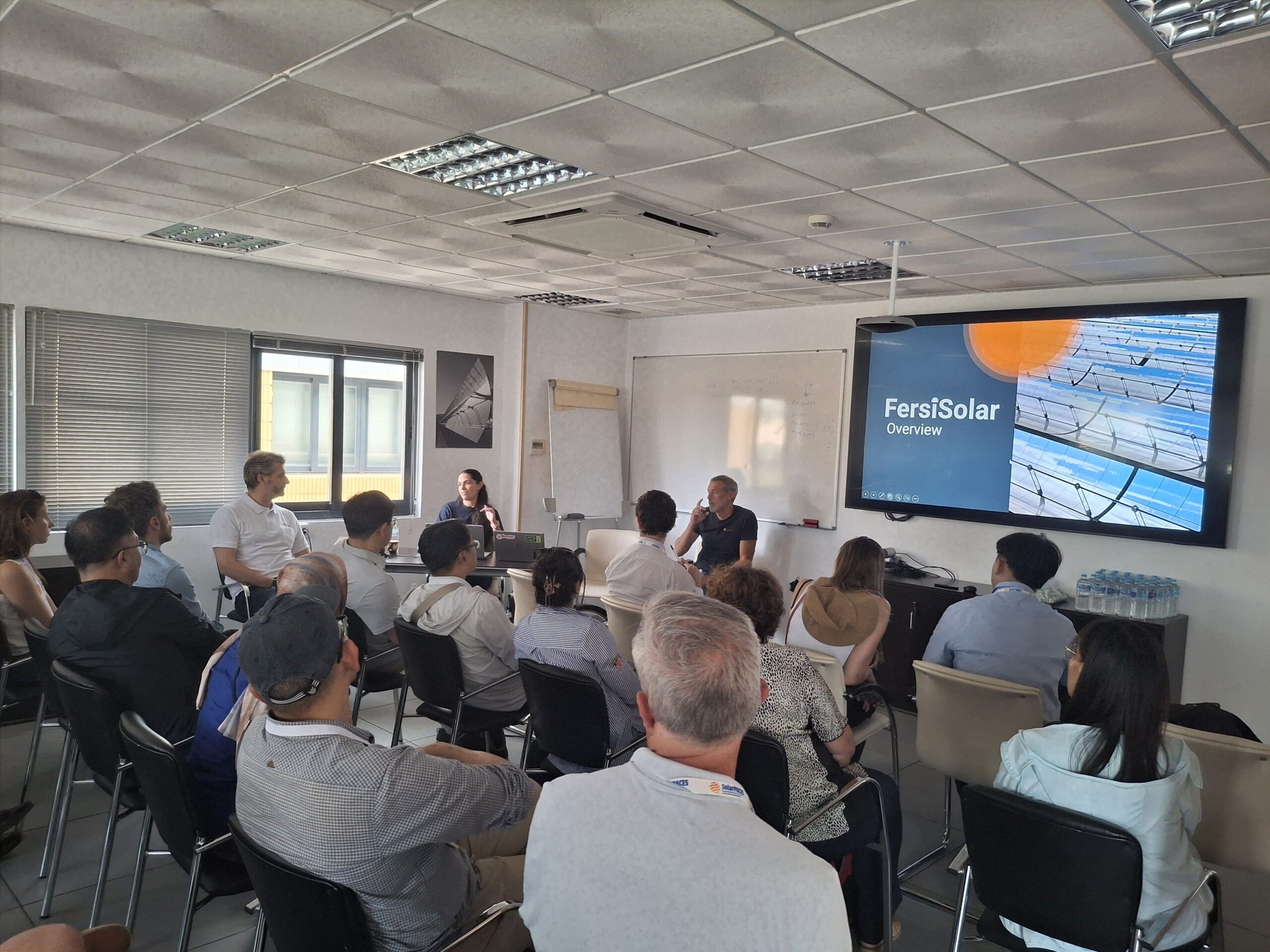
Picture 2: Presentation in the meeting room

After that, the visit continued with a presentation by Marquesado Solar on how they operate the power plant. The participants had the opportunity to ask questions directly to one of the plant engineers, which resulted in a lively discussion about the practices adopted by Marquesado, as well as the challenges that solar thermal power plants face in Spain.

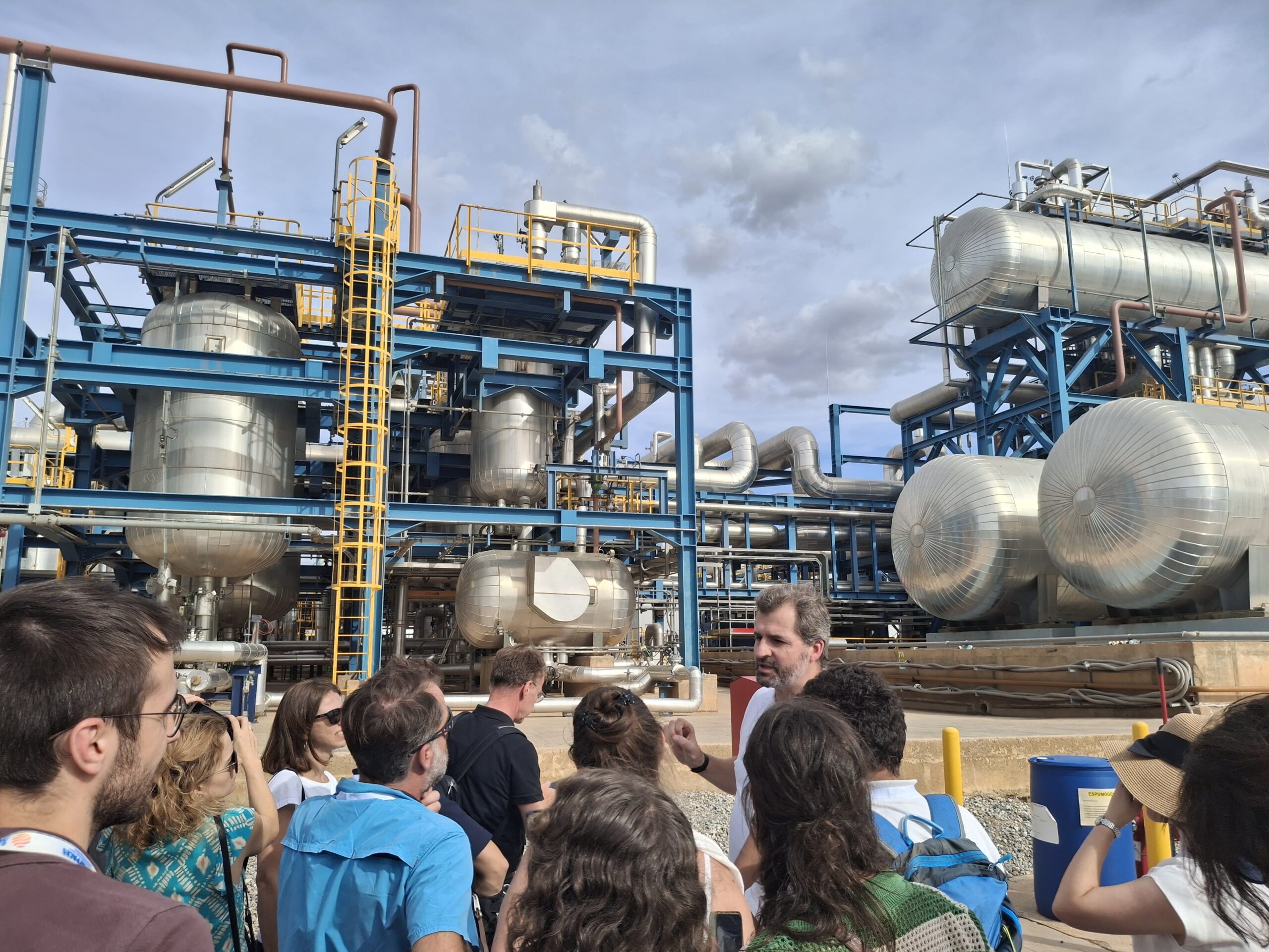
Picture 3: Christiaan explaining the design of the ullage system (left) and the HTF expansion tanks (right)

Lastly, the tour ended with a walk around the power block, where Christiaan Bartels-Mijnhart explained the role and design of different components, like the ullage system for heat transfer fluid, the heat exchangers of the molten salt thermal energy storage, and the gas boilers used to maintain the temperature of the thermal oil.

About Andasol 3

Andasol 3 is a 50 MW parabolic trough solar thermal power plant located near Aldeire and La Calahorra in Granada, Spain. Its solar field covers about 500,000 m² with parabolic mirrors that concentrate sunlight to heat a thermal oil circuit. It has four subfields of collectors oriented along a north-south axis. Energy is stored in 29,000 tons of molten salt, enabling the plant to operate at full capacity for over seven hours after sunset. The plant was constructed between 2008 and 2011 next to the Andasol 1 and Andasol 2 power plants and provides employment for about 50 people since then. Situated at an altitude of 1,100 meters, with abundant solar irradiation, access to Sierra Nevada cooling water, and a nearby electric substation, Andasol 3 remains a benchmark in CSP with storage.

About SolarPACES

SolarPACES (Solar Power and Chemical Energy Systems) is an international network founded in 1977. Its membership comprises research institutions, industry stakeholders, and policy experts working to advance CSP technologies, so they become cost-competitive, reliable, and deliver a dispatchable form of clean energy. SolarPACES coordinates global R&D efforts, publishes strategic studies, and provides guidance to policy makers to reduce the risks in project development. While the organization has historically been focused on generating electricity with CSP, it is increasingly emphasizing high temperature concentrating solar thermal (CST) for industrial heat, and solar thermochemistry for fuels production.

This pivot is occurring as part of a growing recognition that the decarbonization of heat consumption is the next frontier of the energy transition. Industrial heat consumption is an especially thorny subject, as companies are particularly sensitive to the cost of thier inputs, energy included. As 16% of the total final energy consumption of the EU is dedicated to heat production in industries, governments and engineers are hard pressed to offer an alternative to natural gas that can simultaneously reduce emissions and ensure competitiveness. In this context, CST is emerging as a key solution for eco-friendly thermal generation in the industrial sector. It can deliver heat for decades with a stable and predictable cost, shielding its user from the fluctuations of fossil fuel markets.

FersiSolar’s First Sale of Huiyin Receivers (Heat Collection Elements)

In Fall 2025, FersiSolar has successfully managed the first order of Huiyin receivers (Heat Collection Elements, HCEs) for a concentrated solar power plant. This is a major achievement for the Spanish company, which is committed to concentrated solar thermal energy and technical advisory services for CSP projects worldwide. Replacing damaged HCEs improves plant productivity, extends equipment lifetime, and enhances facility safety.

Receivers, or Heat Collection Elements (HCEs), are a key component in these plants, as they capture and transfer the heat generated by concentrated solar collectors to the heat transfer fluid (HTF). Huiyin receivers are recognized worldwide for their high reliability and come with a long performance warranty. They also feature a highly proven vacuum regeneration system.

After the solar thermal company signed the order, Toni Fersini, CEO of FersiSolar, commented:

“This is a very important milestone for us as experts in concentrated solar. It comes less than six months after signing the agreement with Huiyin, and we hope there will be more orders in the coming months. Being a Huiyin sales agent fits with our goal of providing personalized advice to CSP plant operators and helping them improve their facilities. Spain is already one of the leaders in electricity generation from concentrated solar power, and we are committed to keeping these plants in good condition. Concentrated solar power has great potential, and we want to use it to decarbonize industrial heat consumption and continue the replacement of fossil fuels.”

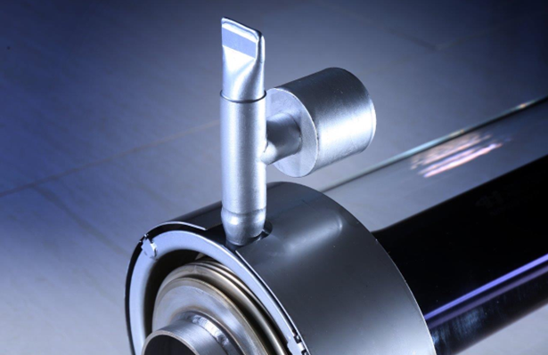
Figure 1: Huiyin receiver (Heat Collection Element)

Juha Ven, President of Huiyin, also expressed his satisfaction:

“It is a pleasure to work with FersiSolar. This first order is an important step in our collaboration. Spain is a strategic market for us, and we look forward to working with more plants in the near future through this partnership.”

About ShanDong Huiyin Energy

Huiyin is a Chinese company specializing in concentrated solar power, founded by the Ven family, originally from Belgium. The family patriarch, Livien Ven, an automation engineer, was the initial driving force behind the group’s activities in the CSP sector. For more than four decades, the Ven family has been actively involved in the development of concentrated solar power (CSP) technologies, building a strong track record in the field.

Huiyin has established itself as a reference company for CSP solutions, drawing on the legacy and accumulated knowledge of the Ven family. This combination of a long-term family vision and a specialized technological focus has been key to building a strong offering in the renewable energy market.

Its main product is receivers (HCEs), which have been supplied to projects with a combined capacity of more than 600 MW. In Spain, the company has sold 3,000 HCEs for concentrated solar projects producing both electricity and renewable industrial heat.

About FersiSolar

FersiSolar was founded on the extensive international experience of its founder, Toni Fersini, in the concentrated solar power sector. Its objective is to make this accumulated experience available to asset owners, investment funds, and financial institutions.

The company is built around three key pillars: advisory services for CSP plant operation and maintenance companies, engineering and technical consulting for solar energy solutions, and sustainable heat supply for industry.

Its mission focuses on providing renewable and innovative solutions for medium- and large-sized industries, providing advice throughout the entire energy facility lifecycle — from development through operation. FersiSolar is committed to providing fully renewable thermal energy and helping achieve independence from fossil fuel consumption through 100% renewable solutions.