

Can Concentrated Solar Thermal Cooling Reduce Electricity Use in Industrial Refrigeration?

Could cooling demand be decarbonized?
Cooling demand is increasing across industrial processes and buildings, driven by higher ambient temperatures and tighter process control requirements. Today, most of this demand is met through vapor-compression systems, the same principle used in standard air conditioners and refrigerators, in which an electrically driven compressor circulates a refrigerant.
Because vapor-compression systems are electrically driven, higher cooling demand increases electricity consumption and can add to peak electrical loads. In many regions, cooling demand peaks when temperatures are highest, increasing electrical load during periods when grids may already be constrained.
For industrial facilities that require both process heat and cooling, thermally driven (absorption) cooling can help decarbonize industry without shifting additional cooling demand to electricity.
What Is Absorption Cooling and How Does It Work?
Absorption cooling provides an alternative by producing cooling from heat rather than electricity. This article focuses on heat-powered absorption chillers, which use thermal energy to drive the cooling cycle.
Conceptually, the thermodynamic objective remains the same as in conventional refrigeration systems: heat is removed from a low-temperature source and rejected to a higher-temperature sink. What changes in an absorption chiller is the way the cycle is driven.
Instead of mechanical compression, thermal energy drives the separation and circulation of the working fluids. Heat absorbed from the chilled water circuit is ultimately rejected through the cooling water circuit.
We’ll dive into the details of the thermodynamic cycle below.
Where Is Cooling Used in Industrial Processes?
Cooling is required at specific temperature ranges and process stages, depending on the sector and operation.
In the food and beverage industry, cooling is required across multiple stages: rapid cooling after thermal treatment, preservation at around 2–8°C, freezing below 0°C, and fermentation control between roughly 5 and 30°C. Additional cooling is often applied before packaging to stabilize product conditions.
In sectors such as paper, chemicals, and pharmaceuticals, cooling is directly linked to process control. It is used to remove heat from equipment and process streams, maintain reaction temperatures, condense vapors, and support crystallization or separation processes. In chemical and pharmaceutical applications, temperature control may range from low refrigeration levels (2–8°C or below) up to controlled cooling near ambient conditions.
Cooling demand is part of the process itself, with requirements determined by production, safety, and product quality.
Can Concentrated Solar Thermal (CST) Supply Industrial Cooling?
Concentrated solar thermal (CST) can provide the thermal energy required to drive absorption chillers. A solar field transfers heat through a thermal fluid to a heat exchanger connected to the chiller, often supported by thermal energy storage (TES) to extend operation beyond solar hours. Depending on the required operating profile and solar contribution, the system may also include backup heat supply.
For plants already considering industrial heat with concentrated solar thermal energy, the same CST field can supply process heat and thermal energy to an absorption chiller. This allows concentrated solar thermal energy to address both process heat and cooling demand within the same thermal system.
This is particularly useful for CST for industrial decarbonization where a plant has both thermal and cooling requirements: concentrated solar thermal heat can replace part of the fossil-fuel heat supply while also driving absorption cooling.
What Are the Main Components of an Absorption Cooling System?
From a technical standpoint, the system is composed of heat exchangers, pumps, cooling towers, and absorber–generator units.
The distinction between conventional and absorption-based cooling is illustrated in Figures 1 and 2.
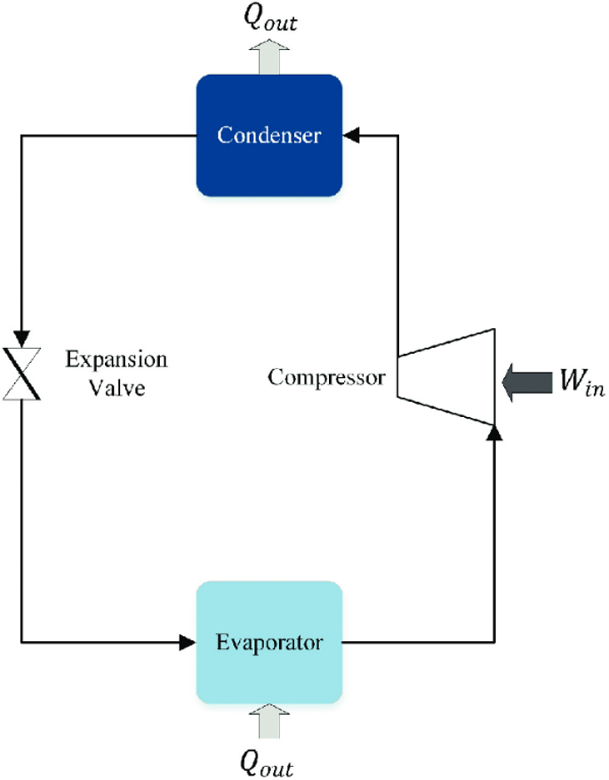
Figure 1: Basic vapor-compression cooling system schematic diagram.
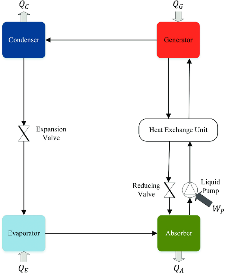
Figure 2: Basic absorption cooling system schematic diagram.
The system can be understood through three interacting loops:
- Refrigerant loop, where cooling is produced through phase change
- Solution loop (LiBr), enabling absorption and regeneration
- Auxiliary loops, including chilled water, cooling water, and heat input
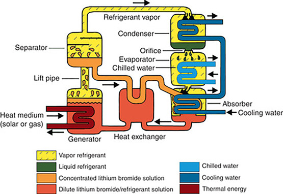
Figure 3: Single-effect LiBr absorption chiller
The configuration described here corresponds to a single-effect absorption chiller, the most common type, operating with moderate-temperature heat input and typically based on LiBr–water as the working pair.
How Does an Absorption Chiller Work?
The system operates with a water–lithium bromide pair, where water acts as the refrigerant.
Evaporator – where cooling is produced
The refrigerant enters the evaporator at higher pressure and temperature and expands into near-vacuum conditions. This rapid pressure drop, from around 101.3 kPa (ambient) to approximately 0.7–1 kPa, causes flash evaporation and a corresponding drop in temperature.
Under these conditions, water boils at 4–7°C, allowing heat to be absorbed from the chilled water loop. This is where cooling is produced.
Figure 4 illustrates the pressure–temperature relationship that enables low-temperature evaporation.
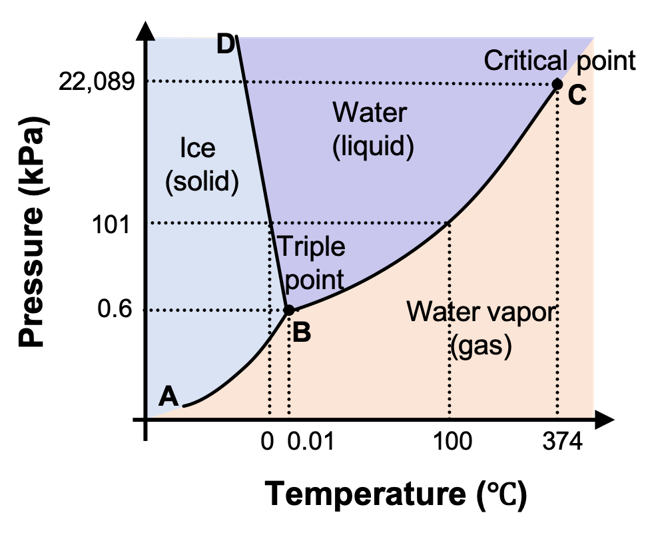
Figure 4: Water phase diagram (pressure vs. temperature)
Absorber – maintaining the cycle
The vapor enters the absorber, where a concentrated LiBr solution absorbs the water vapor, forming a diluted solution. LiBr has a strong affinity for water, which allows the solution to absorb the vapor from the evaporator. The absorber operates at around 30–40°C and pressures close to 1 kPa.
Heat is released during absorption and removed through the cooling water loop. This maintains the low-pressure conditions required in the evaporator.
Figure 5 shows the thermodynamic behavior of the LiBr–water system.
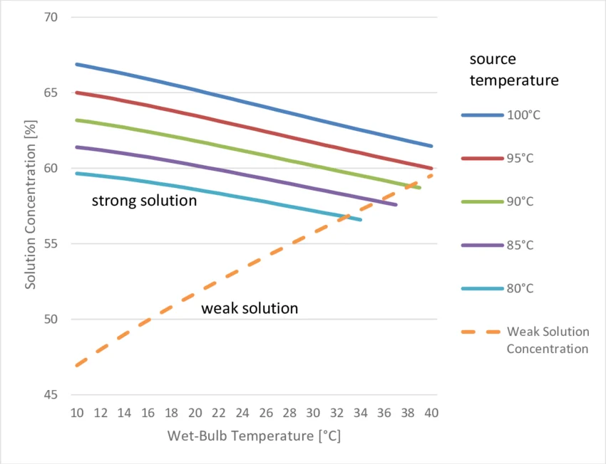 Figure 5: Dühring diagram for LiBr–water solution
Generator – heat-driven separation
The diluted solution is sent to the generator, where thermal energy is supplied. At temperatures of 80–110°C and pressures of 6–10 kPa, the refrigerant separates from the solution, regenerating the concentrated absorbent.
This step replaces mechanical compression with thermal energy.
Condenser – closing the loop
The refrigerant vapor condenses at 30–45°C, rejecting heat through the cooling water loop. The liquid refrigerant returns to the evaporator, while the regenerated LiBr solution returns to the absorber, completing the cycle.
The diluted solution is sent to the generator, where thermal energy is supplied. At temperatures of 80–110°C and pressures of 6–10 kPa, the refrigerant separates from the solution, regenerating the concentrated absorbent.
This step replaces the role of a compressor by using heat instead of mechanical work.
How Can CST-Driven Cooling Be Integrated into Industrial Processes?
Industrial systems frequently combine process heat with cooling and refrigeration needs, as seen in sectors such as food, chemicals, pharmaceuticals, and manufacturing. Cooling requirements range from low-temperature preservation to process-specific temperature control and heat removal.
For plants using concentrated solar thermal energy for industrial processes, absorption cooling provides another use for the thermal energy generated by the CST field. Instead of supplying process heat alone, concentrated solar thermal (CST) heat can also drive cooling where the plant requires it.
Although absorption cooling is a mature technology, its use with concentrated solar thermal energy remains relatively limited. Integrating absorption cooling with concentrated solar thermal (CST) can help decarbonize industrial heat and reduce fossil-fuel consumption without adding the same peak electrical load associated with vapor-compression cooling.


