Solar heat for the minerals industry

The production of gypsum requires a constant heat supply to ensure product quality and process efficiency. Concentrated solar thermal energy with thermal energy storage offers an alternative to gas for industrial processes in the minerals sector. With this technology, it is possible to generate hot air and reach temperatures of up to 400°C, achieving 78 percent thermal coverage or more at the plant.

In addition to providing renewable heat for the minerals industry, a concentrated solar system can help avoid energy volatility in industry, as it provides predictable costs with solar energy and a low levelized cost of heat (LCOH). This makes competitive solar heat for factories a viable option for reducing emissions of greenhouse gases and pollutants and improving the sustainability of production.
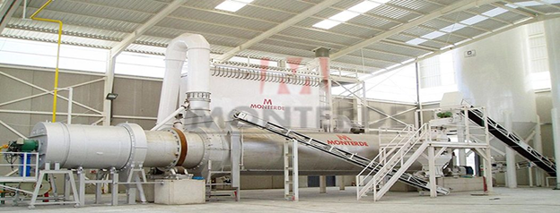
 

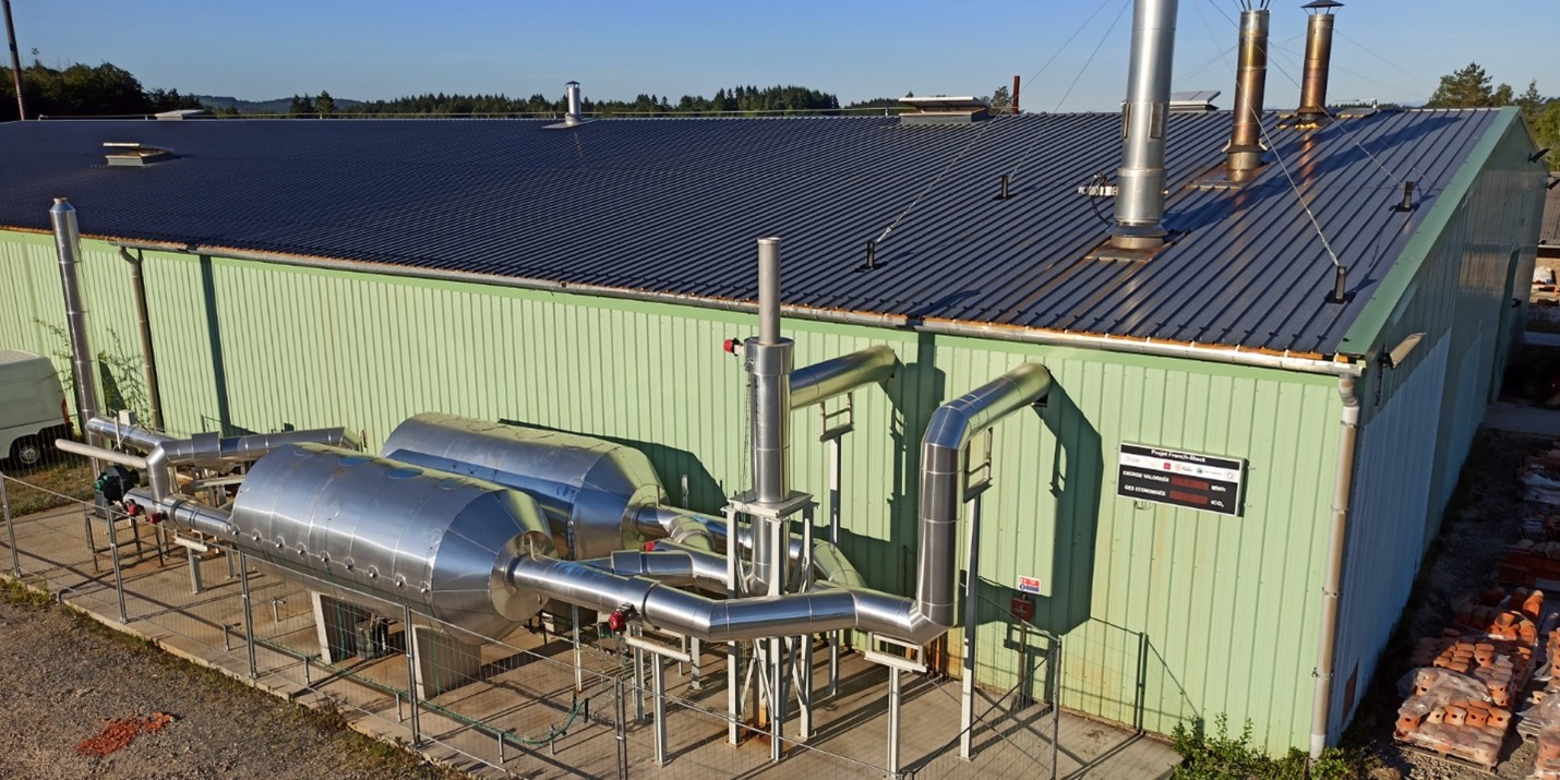
Figure 1: Example of a rotary kiln

And how do we decarbonize gypsum production in practice? First, we have to dry gypsum rock, a sedimentary rock composed of calcium sulfate and water. In this specific case, we need hot air at 300°C and a rotary kiln (Figure 1) to obtain different materials used in construction.

Heat generation
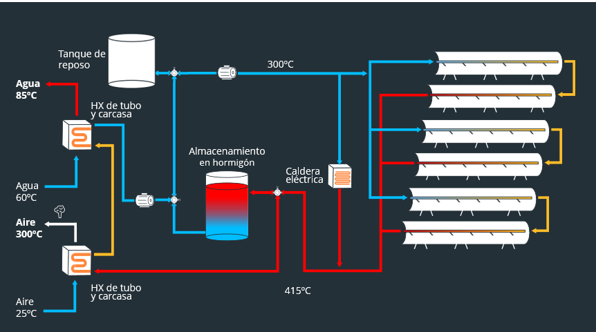
Figure 2: System schematic

As always, we start with heat generation (Figure 2), and for this we use parabolic trough collectors (PTCs). We have already discussed how they work in a previous article (here), so we will not go over the basics again. Unlike the previous cases described, in this project we need to supply heat at temperatures above 250°C, the practical limit of pressurized water as a working fluid. To reach this temperature, we use thermal oil designed to operate at up to 425°C. This silicone-based product has a higher boiling point than water—380°C at atmospheric pressure. We still need to keep the system under pressure for safety reasons, but at pressures below the 40 bar used in the water system.
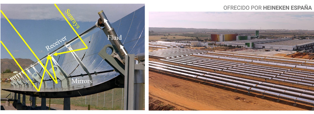
Figure 3: Parabolic trough collectors

Since this project operates at very high temperatures, it is essential to insulate the collector properly to prevent energy losses. The solar collector receiver is a tube onto which the solar rays are focused. As the working fluid passes through this tube, its temperature rises. If the tube is in contact with the atmosphere, some of the concentrated heat escapes through convection; the loss is proportional to the difference between the temperature of the tube and the ambient air.

In projects where the tube and fluid reach temperatures of 150–170°C, the tube can be insulated by placing it inside another transparent tube filled with a noble gas such as argon. However, at temperatures above 200°C, argon cannot provide sufficient insulation, and vacuum insulation technology is required. In Figure 4, the metal tube containing the working fluid is shown in purple; this tube is housed inside another glass tube, with an insulating vacuum between them. This type of receiver is more expensive and less reliable than receivers without insulation, but its use is essential to prevent prohibitive heat losses.
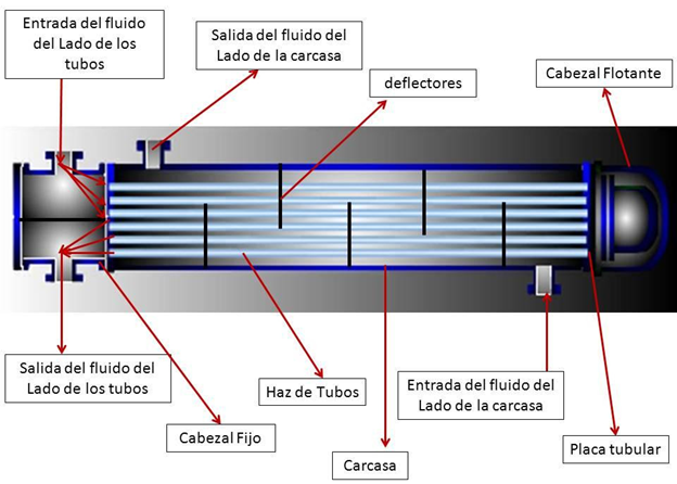
Figure 4: Schematic of a vacuum-insulated absorber tube

Storage system

Once the heat has been generated, it must be stored until it is needed. Thanks to the concrete thermal energy storage system (TES), it is possible to ensure 24/7 operation and process continuity, even when there is no sunlight. In this case, the thermal battery can supply all the heat required by the kiln for up to 12 hours without needing to be recharged. Due to the high temperatures of the stored heat, the TES is made of concrete. In basic terms, we have a concrete block with integrated pipes (Figure 5). During charging, the working fluid from the solar field flows through these pipes, heating the block. During discharge, the cold fluid enters through the same pipes and is heated by absorbing heat from the block.
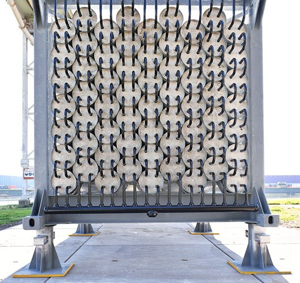
Figure 5: The ThermalBattery from EnergyNest

Unlike a water TES, concrete has lower convection losses; in addition, the system is simple, robust, and economical. However, the concrete formulation must be optimized to achieve the desired properties and maximize performance. Two parameters are key:

  • Thermal conductivity: the higher it is, the faster the TES charges and discharges. It can be improved by modifying the type and particle-size distribution of the aggregates, adjusting the proportions of the concrete components, or adding additives such as conductive fillers or fibers.
  • Specific heat capacity: the higher it is, the more energy can be stored per unit of mass. It can also be optimized by changing the type and grading of the aggregates and the composition of the mixture.

In addition to their low cost, concrete TES systems eliminate the risk of leaks compared with tanks containing liquids such as water or molten salts. Their main disadvantage is that, because concrete is a solid, a minimum temperature difference of 25–30°C between the temperature of the flowing fluid and the concrete is required to achieve adequate heat exchange. This temperature difference is present during both charging and discharging, which means that the fluid received by the customer has a temperature at least 50°C lower than the fluid leaving the solar field.

Energy supply, standby, and conclusion

To supply heat to the customer, we use two shell-and-tube heat exchangers, equipment that we have already described previously (here). The first operates at a higher temperature and heats the air used in the kiln to 300°C. After leaving this heat exchanger, the thermal oil enters the second unit to heat water to 80°C. This water is used for other industrial processes, provides sanitary hot water for workers, and, during winter, is used to heat the factory buildings. Once all the energy has been extracted from the thermal oil, it is stored in a tank until its next circulation through the solar field. This tank serves a second purpose: it is sized so that it is never completely full, allowing it to accommodate the expansion of the thermal oil that occurs when it is heated.

Thanks to this heat storage and distribution configuration, the system ensures a continuous and efficient thermal supply for all the customer’s processes. With it, we have achieved a solar coverage of 78% of thermal demand, placing our customers at the forefront of decarbonization, both in the minerals industry and across the raw materials sector.

At FersiSolar, we know how to design, build, and operate such plants and help you decarbonize your industrial heat consumption. The time to act on climate change is now, and the solution already exists. Contact us.

Calor solar para la industria de pintura

La integración de energía solar como fuente de calor industrial en una planta de manufactura de pinturas representa una solución viable para avanzar hacia una industria de pintura con cero emisiones. En este proyecto estudiamos la viabilidad de implementar un campo solar térmico capaz de suministrar aire caliente industrial con energía solar a 200ºC, cubriendo gran parte de la demanda térmica del proceso.

Este tipo de solución permite la descarbonización de procesos térmicos industriales y ofrece una alternativa competitiva con un coste nivelado del calor solar industrial (LCOH) alrededor de €20/MWh. Esto muestra claramente la viabilidad económica del calor solar en sectores con alta demanda térmica como este. No solo promovemos el ahorro energético, sino que también mejoramos las expectativas económicas del cliente.

¿Y cómo lo hacemos en práctica? Los ingredientes más importantes en la producción de pintura son:

  • Resina – se utiliza para unir el resto de los componentes y otorgarle a la pintura sus cualidades adhesivas.
  • Disolvente – actúa como transportador de los demás componentes. A medida que la pintura se seca, el disolvente se evapora y la solución se solidifica.
  • Pigmento – da el color a la pintura.
  • Aditivos – se incorporan para que la pintura sea más fácil de usar, y le otorgan diversas cualidades útiles, como un secado rápido y resistencia a las grietas y las rozaduras.

Desde el punto de vista energético, la resina es la más importante de todos estos ingredientes. Su producción contiene varios procesos que necesitan aire y agua caliente con temperaturas alrededor de 200ºC y 80ºC respectivamente para el secado. Te mostramos como se descarbonizan abajo.

Generación del calor

Empezamos con la generación del calor, y para esto utilizamos Captadores cilindroparabólicos (CCP). Ya hemos discutido como operan en un texto previo (aquí), así que no vamos a sumergirnos profundamente otra vez. Lo importante es que en el campo entra agua a unos 122ºC y el este la lleva a 245ºC, abasteciendo de manera económica unos 70% de la demanda anual de calor en la planta. Los 30% que sobran se pueden proporcionar por una caldera eléctrica para completar la descarbonización, o por la caldera de gas natural que ya estaba presente en la fábrica.

Ilustración 1 Captadores cilindroparabólicos

Sistema de almacenamiento

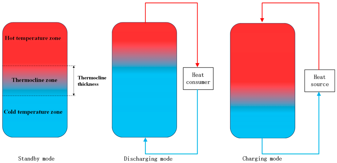
Gracias al sistema de almacenamiento térmico solar, es posible garantizar la operación 24/7 y la continuidad de los procesos, incluso en ausencia de sol. En este caso, la demanda térmica del cliente es relativamente baja (56 GWh/año), que permite la instalación de un sistema de almacenamiento (TES) con tanque termoclina. Esta tecnología se caracteriza por el uso de un solo tanque que alberga tanto el agua caliente procedente del campo solar, como el agua fría que tiene pendiente entrar allí y calentarse. Los dos tienen una densidad diferente a causa de su temperatura diferente, que les permite estar separados. Se forma una capa, llamada la termoclina, con gradiente térmico pronunciado entre las partes caliente y fría del tanque (Ilustración 2).

Ilustración 2: Operación de tanque de almacenamiento con termoclina

La tubería del tanque está conectada de modo que refuerza la separación – cuando el sistema se carga, el agua caliente entra por la parte superior del tanque y permanece allí por su densidad baja. En períodos de descarga, el agua fría que ha pasado su energía al cliente entra por la parte baja del tanque y se mantiene allí a causa de su densidad alta. El esquema arriba visualiza estos modos de operación.

Los sistemas con tanque termoclina tienen una clara ventaja económica frente los sistemas de almacenamiento con dos tanques. Simplemente necesitan la mitad de tuberías y tanques, que se equivalente a unos costes menores. Su desventaja principal es que ofrecen un peor nivel de control de la temperatura de los flujos salientes y, además, tienen un límite práctico en su tamaño: más allá de ciertas dimensiones, mantener una capa de termoclina definida y estable se vuelve técnicamente complicado debido a la dinámica de fluidos y los efectos de difusión del calor.

Suministro de energía

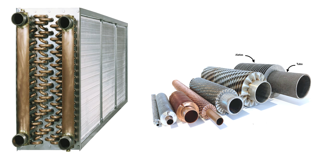
Para suministrar el aire caliente al cliente, tenemos que resfriar el agua saliente del campo solar y transferir su energía al aire y para esto utilizamos un intercambiador de calor. Los intercambiadores de serpentín son especialmente eficientes en este ámbito, gracias a su larga superficie de transferencia. El intercambiador consiste en tubos por donde pasa el agua caliente (Ilustración 3, derecha). Los tubos tienen aletas de metal que extienden su superficie y mejoran la transferencia de calor al aire. Toda esta tubería se monta en una instalación con rejas para reducir el ensuciamiento de las aletas. En la ilustración abajo se ven claramente los dos pares de entradas y salidas del fluido (los cuatro tubos en las esquinas del intercambiador) y la reja detrás. Ventiladores grandes crean un corriente de aire que pasa en dirección perpendicular a los tubos en una serie de intercambiadores como este. El aire con temperatura ambiental entra por un lado y sale a 200ºC por el otro.

Ilustración 3: Tubos de intercambiador con aletas (derecha) e intercambiador completo (izquierda)

El agua que sale del serpentín todavía está bastante caliente y tiene mucha energía térmica. Para aprovecharla, se puede usar un intercambiador de calor tipo tubo y carcasa (Ilustración 4). En este sistema, el agua caliente fluye por los tubos o por la carcasa, mientras que el otro circuito de agua (el que queremos calentar) circula en la parte opuesta. El calor se transfiere a través de las paredes de los tubos sin mezclar los fluidos, calentando así eficientemente un segundo bucle de agua para otros usos en la planta. Una vez sacado el calor, esta agua llega a través de una línea de retorno al intercambiador de calor para repetir su ciclo.


Ilustración 4: Intercambiador de calor de tubo y carcasa

Reposición de agua y conclusión

Con todo el calor transmitido al cliente el agua fría (en el contexto del sistema, por lo menos) vuelve al tanque termoclina para esperar su siguiente vuelta. En este caso, el sistema solar térmico funciona en un circuito cerrado. Es decir, el agua circula únicamente entre el campo solar, el tanque de almacenamiento y los intercambiadores de calor con el cliente, sin salir del sistema. Como el sistema requiere que el agua cumpla con características específicas y no podría funcionar de forma segura con agua tomada directamente de la red, es bastante ventajoso operar en circuito cerrado. Así basta con tratar una sola vez el volumen inicial de agua, y únicamente se requiere reponer pequeñas cantidades en caso de pérdidas, reduciendo significativamente los costes de desalinización y el control del contenido químico del agua.

Y eso es todo: así funciona este tipo de sistema para la producción de aire caliente con almacenamiento térmico. Hemos logrado una cobertura solar del 70 % de la demanda térmica, posicionando a los clientes como pioneros en la descarbonización tanto de la industria de pinturas como del sector químico en general.

En FersiSolar sabemos cómo diseñar, construir y manejar tales plantas y ayudarte a descarbonizar tu consumo de calor industrial. El momento de actuar por el clima es ahora, y la solución ya existe. Contáctanos.

Solar Industrial Heat

We have often discussed the importance of decarbonizing process heat in industry and argued that concentrated solar thermal energy could play an important role in this. But how are fossil fuels actually replaced in practical terms? In this text, we dive into the topic.

Above is the schematic that will guide us. We will focus on a case in which we provide industrial heat in the form of steam at 180°C and hot water at 85°C. Temperatures such as these are typical for the food industry and are the focus of different industrial decarbonization projects. For example, in Seville, parabolic trough collectors produce pressurized hot water at a temperature of 210°C, while in Finland, an electric system at the Herkkumaa Oy plant produces steam at 180°C. Ideally, the system will provide heat at two different temperatures to achieve the highest possible energy efficiency.

Heat Generation

We start with heat generation, for which we use parabolic trough collectors (PTC) or linear Fresnel (LF) collectors. Both are linear concentrating solar technologies that work by reflecting solar radiation towards a receiver tube through which a thermal fluid flows. In the case discussed in this text, where we would like to produce steam at around 180°C, the working fluid would be pressurized water.

Water enters the field at around 95°C, and the field heats it to 245°C (we will discuss later why 245°C rather than 180°C). At higher temperatures, thermal oils would be required, but at such relatively low temperatures there is no problem using water, which is cheaper and easier to operate.

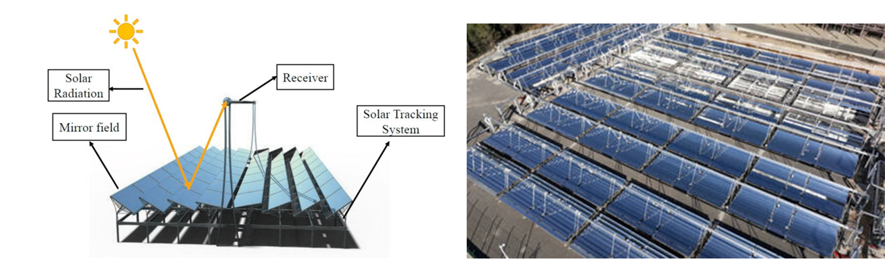
Parabolic trough collectors (Figure 1) use curved, parabolic-shaped mirrors along a longitudinal axis. These mirrors track the movement of the sun throughout the day and concentrate solar radiation onto a focal line where the receiver tube is located. This tube is covered by a glass envelope to reduce thermal losses and contains the water being heated. The solar field would consist of rows of collectors that heat the water to the desired temperature. Adding more rows in parallel increases the system’s capacity. Compared with linear Fresnel collectors, PTCs are more efficient at converting solar energy into heat and therefore require less space to provide the same capacity.

Figure 1: Parabolic trough collector (left) and solar field of collectors (right)

In contrast, linear Fresnel collectors use multiple flat or slightly curved mirrors arranged in parallel rows on the ground. Each mirror is independently oriented to reflect sunlight towards a fixed receiver tube located on an elevated structure. Although solar concentration is not as precise as with parabolic troughs, Fresnel systems have lower material costs and a lighter design, allowing them to be integrated even into industrial plant rooftops.

Figure 2: Linear Fresnel collector and collector field

Before closing this section, we should not forget that the solar field could not economically provide 100% of the required heat. Another system operating in parallel with the solar system is needed and can be activated whenever solar thermal energy is insufficient. This could be the fossil fuel boiler that was replaced when the solar thermal system was installed, in order to avoid additional costs, or it could be an electric or biomass boiler to achieve full decarbonization.

Ultimately, solar thermal energy is one of the tools available to reduce the use of fuel oil and natural gas in industry and lower its carbon footprint, but it is not the only one. These other renewable energy sources can be used in conjunction with solar thermal energy in cases where there is limited space available near the plant or where solar irradiation is low.

Storage System

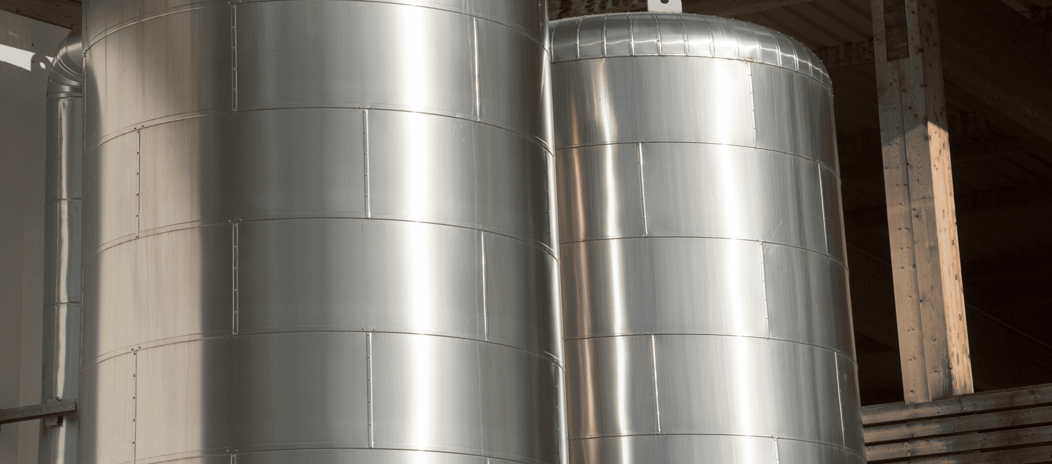
Once we have generated the heat, we need to store it until the appropriate time for use. The simplest approach would be to have a well-insulated tank and store the pressurized water coming from the solar field directly in it. This avoids the need to install a heat exchanger to transfer heat from the water to the material used by the Thermal Energy Storage (TES) system.

Figure 3: Pressurized water thermal energy storage tanks

So why do we produce water at 245°C? First, if we need to provide steam at 180°C, it is important to have a higher temperature in the TES to ensure that we can always extract at least 180°C, even when the solar field has not been operating for some time and the temperature in the tank has dropped somewhat.

Second, when extracting heat from a material by cooling it, the amount of energy depends on the difference between the initial and final temperatures (Thot – Tcold). If Thot increases by 70% while Tcold remains unchanged, the same amount of material could store approximately 70% more heat. This is important because a larger TES will also be more expensive.

Would it be better to increase the production temperature even further, rather than stopping at 245°C? First, keeping water liquid at 245°C requires considerable pressures of around 40 bar. Increasing the temperature further means increasing the pressure, which requires stronger and more expensive components. Second, safety regulations become more stringent as pressure increases, for obvious reasons, making the system even more expensive.

Taking everything into account, 245°C is a temperature that balances these factors and allows us to use a reasonably sized storage tank that remains sufficiently cost-effective.

Energy Supply

We have reached the desired point of supplying the generated heat to the industrial consumer. Starting with steam, the simplest way to produce steam from pressurized water without increasing its temperature is to reduce the pressure (flash evaporation, or steam flashing) by introducing the water into a flash chamber. What happens is that, at lower pressure, the boiling point of water decreases — and because the water was already hotter than this new boiling point, part of it “boils” instantly without adding any additional heat.

A large portion of the water will remain liquid under the new pressure, so we still have a mixture of liquid water and steam. To separate them, a steam drum is used. This vessel allows the steam to rise and exit through the top, while the denser water falls to the bottom. In this way, clean steam is obtained through an upper outlet and supplied to the industrial plant, while hot water is obtained through a lower outlet.

Figure 4: Shell-and-tube heat exchanger

The separated water still contains useful thermal energy. To recover it, a shell-and-tube heat exchanger (Figure 4) can be used. In this system, the hot water flows through either the tubes or the shell, while the other water circuit — the one we want to heat — flows on the opposite side. Heat is transferred through the tube walls without mixing the fluids, efficiently heating a second water loop for other uses in the plant. Once the heat has been extracted, this water reaches the heat exchanger through a return line to repeat its cycle.

Water Make-Up and Conclusion

Finally, we have the water make-up systems. The system described operates as an open cycle, meaning that the steam used in the industrial process cannot be condensed and reused. Therefore, the system must be continuously supplied with water to compensate for these losses. Upon entering, the water is pressurized to reach the 40 bar at which the system operates. It then enters a supply tank, where it waits until it is ready to enter the solar field.

This is how renewable solar thermal energy can be integrated into industrial heat consumption when heat is required at temperatures below 250°C. The same solar fields can reach up to 425°C with modifications to the thermal energy storage system and working fluid. The industry can be in the food, textile, chemical, paper, or any other sector requiring heat.

At FersiSolar, we know how to help you decarbonize your industrial heat consumption. The time to act on climate is now, and the solution already exists. Contact us.
Ceramics thermal energy storage

Wouldn’t it be amazing to live in a more just and equal society where extreme poverty and hunger are a thing of the past? A future in which our species is not exploiting its environment to the point of tipping the whole planet off balance? The energy transition should be and could be a step in that direction and renewables are a big part of this transition.

TES systems basics

An issue solar technologies face is the intermittency of the sun’s shining, which makes them produce energy discontinuously. The solution best suited to deal with this intermittency in the case of concentrated solar collectors is called thermal energy storage (TES), and we discussed it in depth in our previous publications (one and two).

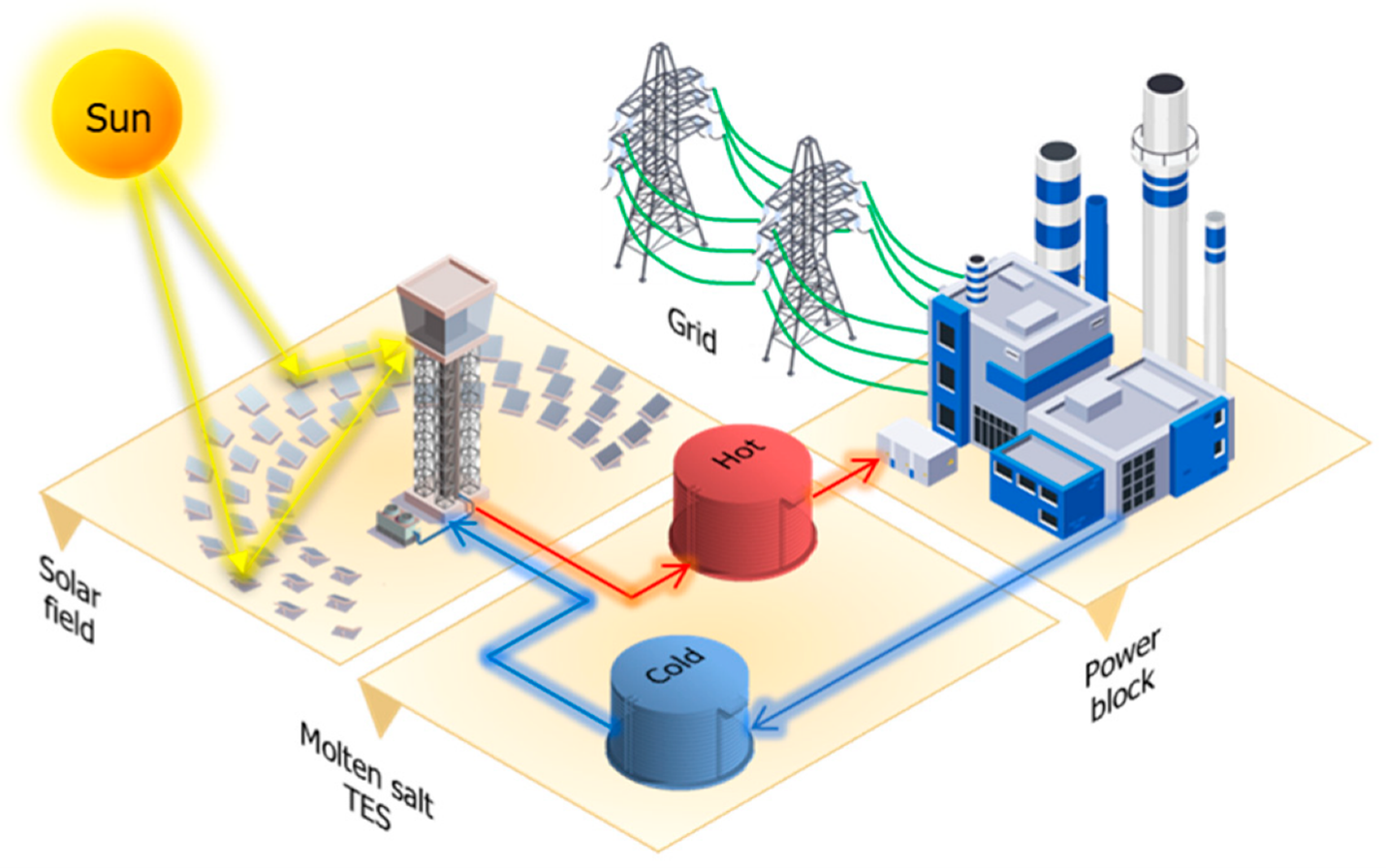
Figure 1: Schematic of a molten salt storage system with two tanks. Source.

The spark notes on sensible heat storage, the type of TES we’ll focus on the most in this article, are that we heat up a material that can absorb a lot of heat without changing its phase and keep it in a well-insulated vessel. The most installed TES technology uses molten salt as a storage medium, a material that can reach a maximum temperature of 565 ºC. Among the benefits of using this technology are its high technological maturity, high efficiency and relatively high energy density. Its worldwide presence and its technological maturity are owed to its usage in concentrated power plants for electricity production. Yet, in the last years, it has also being adapted to decarbonize the heat consumption in industries.

Issues with molten salt TES

Despite its advantages, molten salt TES have certain drawbacks. Among them is the fact that they solidify at temperatures below 200 ºC requiring constant heating to avoid blockages and maintain operability which complicates system design and operation. Another issue is their aggressive corrosiveness, which increases with temperature. It can degrade metal components such as pipes, heat exchangers, and tanks, necessitating the use of expensive, corrosion-resistant materials, which increases capital and maintenance costs. These issues make molten salts a reliable but complex and costly TES solution and open the door for other technologies to be used instead.

Considerable research efforts are being invested to drive the circular economy in the field of thermal storage. Construction and demolition waste, ceramics by-product from the treatment of asbestos, or ceramics made of copper slag and red mud are among the considered materials.

Advantages and Limitations of Ceramic Materials

The primary advantage of ceramics for TES lies in their ability to withstand extremely high operating temperatures – often exceeding 1000 °C – without melting, decomposing, or degrading structurally. This makes them ideal for next-generation TES systems designed for use in industrial waste heat recovery, and electrified heat applications. Additionally, ceramics are generally chemically inert, non-flammable, non-toxic, and resistant to corrosion, making them low-risk materials in terms of environmental safety and long-term operation.

Two key thermophysical properties govern their performance as TES media: thermal conductivity and volumetric heat capacity. High thermal conductivity enables faster charging and discharging cycles, improving system responsiveness and efficiency. At the same time, a high volumetric heat capacity allows more energy to be stored per unit volume. The challenge lies in balancing these properties, as many low-cost ceramics (especially recycled types) have low thermal conductivity, which can limit heat transfer and reduce the usable power output of the system.

Ceramics are also brittle by nature, which makes them vulnerable to mechanical stress and thermal shock — especially under fast or cyclical heating conditions. These issues can be addressed through better design of component geometry (e.g., allowing thermal expansion), or by using engineered ceramics and composites.

System Configurations: Packed Bed Thermoclines

Ceramic materials are most commonly used in packed bed TES systems, where the ceramic elements (e.g., bricks, spheres, pellets) are arranged inside an insulated tank. In this configuration, heat transfer fluid (usually air) flows through the voids between the solid elements, exchanging thermal energy with the storage media. This type of system is simple, cost-effective, and mechanically robust.

Figure 2: Thermocline storage tank schematic. Source.

A frequently used approach is the thermocline configuration, where a single tank is charged from one end and discharged from the opposite end, allowing a temperature gradient to form and move through the bed. If more capacity is needed, multiple units are arranged in parallel. This reduces the need for two separate tanks as used in molten salt systems – one for the hot charged salt and one for the cold salt post discharging – and minimizes material requirements and heat losses.

Current Research and Development

Several major European research projects are focused on ceramic-based TES development. These include the FLUWS project, which investigates radial packed bed designs using recycled ceramics or HIFLEX, which explores ceramic storage for renewable combined heat and power plants. Academic institutions such as KTH Royal Institute of Technology in Sweden and CIEMAT in Spain are active in testing new ceramic formulations, thermal cycling behavior, and integration strategies for CSP and industrial heat applications.

These projects often prioritize the use of recycled ceramic materials — including demolition waste and off-spec tiles — to promote a circular economy while reducing costs and environmental impact. Material validation, performance benchmarking, and system-level modeling are common themes across their research activities.

Real-World Implementation: Eco-Tech Ceram and Kraftanlagen

Beyond the lab, several companies have already deployed ceramic-based TES systems commercially. Eco-Tech Ceram, a French company, has developed a containerized storage solution called the Eco-Stock, which uses refractory ceramics to store the heat of the exhaust fumes. This captured energy is then used in other parts of the industrial process. The Eco-Stock is designed for modular deployment, offering up to several MWh of storage in a mobile, insulated unit.

Figure 3: Ecotech Ceram’s system at Tegulys. Source

Another notable example is Kraftanlagen Energies & Services in Germany, which has implemented ceramic TES systems for industrial clients. Their systems use solid bricks or structured ceramic blocks and can be integrated into steam generation systems, heating loops, or combined heat and power plants. They often work with ceramic suppliers to customize materials and geometries based on specific temperature, cycle, and pressure requirements.

Outlook and conclusion

The field of thermal energy storage is dynamic, with new technologies well on their way. Ceramic-based TES systems represent a resilient and increasingly practical solution for high-temperature energy storage, especially when aligned with circular economy principles. As both research and industry continue to validate their performance and durability, ceramics — particularly recycled varieties — are promising a more sustainable future both for our materials and energy usage. With commercial applications already underway and further innovation on the horizon, ceramics are set to play a central role in scaling sustainable, high-efficiency heat storage across industrial and renewable energy sectors.

At FersiSolar we’re ready to help you install the right thermal energy storage at your plant. Contact us, the world cannot wait.

Almacenamiento térmico industrial, parte II

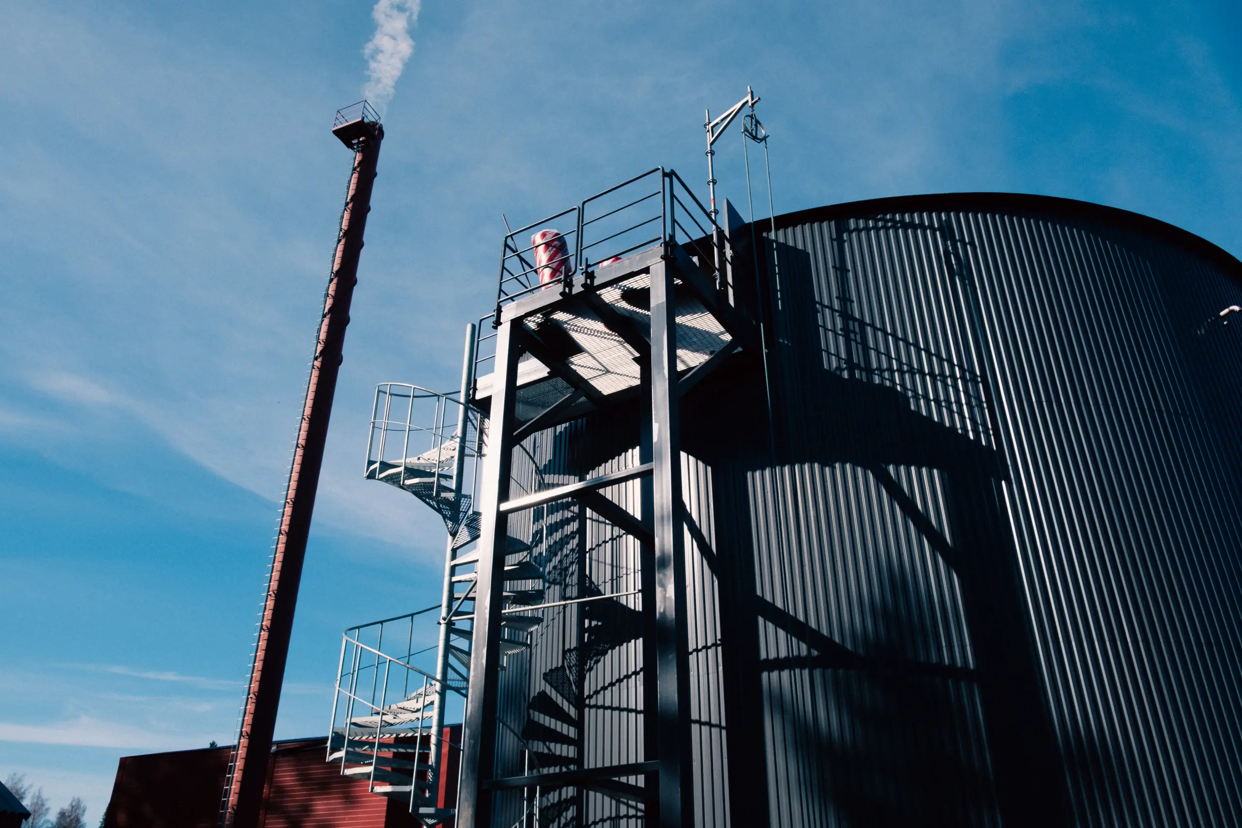
Tanques de almacenamiento en construcción en Hungría. Fuente

En la publicación anterior, hablamos mucho sobre el almacenamiento de calor en las industrias. Establecimos los fundamentos de la tecnología, su nivel de madurez y su impacto ambiental. Pero en ningún momento discutimos de cómo se usan estos sistemas en la práctica, lo cual quizás sea la pregunta más interesante. Si has repasado lo escrito antes, te invito a profundizar en este nuevo artículo.

Aplicación 1: Almacenamiento térmico para la integración de energías renovables en la industria

El sector manufacturero consume grandes cantidades de energía, principalmente de origen fósil. Uno de los papeles importantes del almacenamiento térmico es facilitar la descarbonización de este suministro.

Mediante energía termosolar

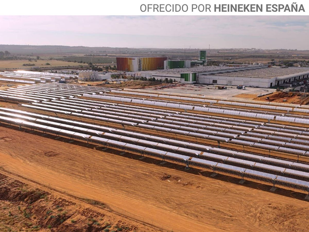
Una opción para conseguir esto es emplear energía termosolar y producir el calor directamente. Esto es lo que hace Heineken en sus plantas en Valencia y Sevilla. En Sevilla la cervecería dispone de 68 MWh de almacenamiento de calor sensible, con ocho tanques de agua presurizada que se cargan mediante 30 MW de captadores cilindroparabólicos. En Valencia la planta es más pequeña, pero usa tecnología similar, con tanque de 1.5 MWh de agua presurizada, generada por captadores Fresnel. En ambos casos se evita la combustión de gas natural.

Ilustración 1: La fábrica de Heineken en Sevilla. Fuente.

Mediante electrificación

La otra manera de conseguir la descarbonización consiste en sustituir la combustión de combustibles por tecnologías que usan electricidad, como bombas de calor o calderas eléctricas. La penetración de energía renovable intermitente en las redes eléctricas, especialmente en España, se traduce en una huella de carbono baja por unidad de electricidad consumida y también, con frecuencia, provoca que los precios de la luz lleguen a cero. Al mismo tiempo, dificulta el balanceo de la red, ya que da lugar a picos de generación renovable en momentos ventosos o soleados.

La incorporación de almacenamiento térmico abre una vía de ahorro de costes para las industrias, al mismo tiempo que impulsa la transición energética. Los equipos eléctricos generan calor en momentos de alta oferta eléctrica, cuando los precios son bajos; este calor se almacena en los sistemas de almacenamiento y se consume según las necesidades de la fábrica. Este tipo de operación tiene el beneficio añadido de estabilizar la red eléctrica, ya que añade consumo en los momentos en que más se necesita.

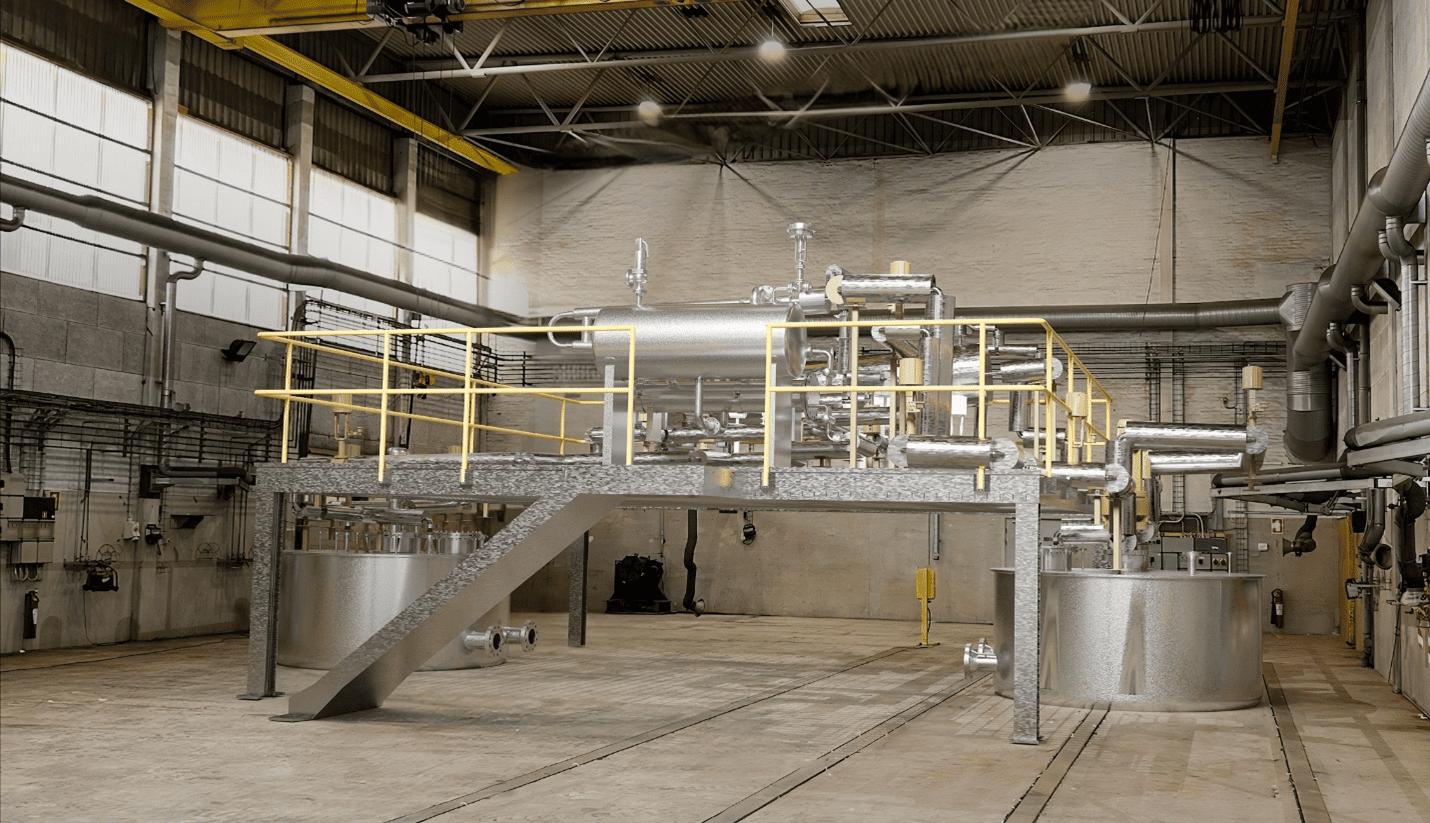
Ilustración 2: La planta de demonstración de Hyme Energy. Fuente.

El proyecto de tecnología escalable de Hyme Energy en la planta de leche en polvo de Holstebro sigue exactamente la misma idea (Ilustración 2). Calentadores eléctricos operarán en momentos de alta penetración de electricidad eólica o solar, acumulando calor en tanques de calor sensible con sales fundidas. Una vez construido, será el proyecto de almacenamiento térmico industrial más grande del mundo, con una capacidad de 200 MWh.

Aplicación 2: Almacenamiento térmico para la utilización de calor residual en las fábricas

El desafío y su magnitud

Después de discutir la energía que “entra” en un proceso industrial, es importante hablar de la energía que “sale”. De origen fósil o renovable, la mayoría de la energía consumida se convierte en calor durante el proceso de fabricación. Este calor se libera a la atmósfera mediante intercambiadores o los gases de escape. Puede valorizarse de múltiples maneras, desde el uso directo del calor a la temperatura disponible, pasando por el empleo de bombas de calor o enfriadoras por absorción para generar calor o frío, hasta la producción de electricidad mediante ciclos Rankine orgánicos (ORC).

Debido a la gran escala del consumo industrial, los beneficios no serían insignificantes; un estudio concluye que ORC podrían producir hasta 20 TWh de electricidad cada año en la UE utilizando únicamente calor que se disipa en la atmósfera. Este ahorro equivale a la producción eléctrica anual de un país pequeño como Islandia, por ejemplo.

¿Y porque hablamos de esto en un texto de almacenamiento de calor? Una de las barreras de usar esta energía es su liberación en tasas de producción no uniformes, con grandes variaciones debidas, por ejemplo, a la producción por lotes. Esto complica el dimensionamiento de los equipos que valorizan el calor residual – si se diseñan para acomodar la capacidad mínima constante, no podrían arrancar en momentos de alta actividad y utilizar la energía extra disponible. Por el contrario, si se diseñan para ser lo más grandes posible, la inversión sería mayor y el equipo operaría con menor eficiencia a carga parcial en la mayoría del tiempo.

El almacenamiento como solución

El uso de almacenamiento puede ayudar con esto, ofreciendo un flujo de energía más estable y con una magnitud óptima. El equipo que valoriza la energía residual se diseña con para esta magnitud y así logra un mejor factor de capacidad – un índice que equivale al 100 % si un equipo se usa a su potencia máxima todo el tiempo, y es del 0 % si no se utiliza nunca. Esto también mejora la estabilidad operativa del equipo y puede aumentar su vida útil al reducir los ciclos térmicos extremos. Por último, el almacenamiento permite desacoplar temporalmente la generación de calor y su uso, facilitando la reutilización del calor residual por otros procesos industriales continuos.

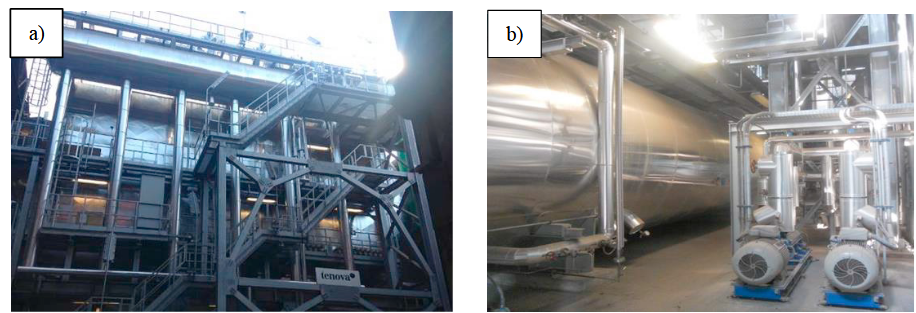
Ilustración 5: (a) Sistema de utilización del calor residual con el tambor de vapor en la parte superior. (b) Vista lateral del acumulador de vapor de 150 m3. Ambos en planta siderúrgica en Brecia, Italia. Fuente

Ejemplos de proyectos comerciales incluyen dos ORC de 1.8 MWe y 2.7 MWe instalados en plantas siderúrgicas de arco eléctrico en Italia y Alemania, respectivamente, con sistemas de almacenamiento térmico de calor sensible con acumuladoras de vapor. En el caso italiano (Ilustración 5), los gases de escape se enfrían al evaporar agua. El vapor entra en el sistema de almacenamiento con el ritmo de producción, pero sale con flujo fijo y calienta el fluido de trabajo del ORC. La electricidad producida se utiliza en otros procesos en la planta y reduce sus costes operativos.

En FersiSolar S.L. somos expertos en energía solar concentrada, almacenamiento térmico y descarbonización industrial. ¿Estás ansioso por reutilizar el calor que tu fabrica tira por la chimenea? Cada grado que reaprovechas cuenta. Escríbenos y te contamos cómo hacerlo.

Almacenamiento térmico industrial, parte I

El almacenamiento térmico en la industria puede generar tanto a un ahorro energético considerable, como a la descarbonización de la energía que consumen las industrias – dos pilares clave de la transición energética. A pesar de todo esto, la mayoría de las personas piensa solo en el almacenamiento de electricidad que sí que tiene un papel clave en la introducción de renovables en la red y ayuda a evitar apagones (aunque eso nunca sería importante, ¿verdad?), pero no es la única vía de almacenar energía. En este texto ponemos el foco sobre el almacenamiento térmico de procesos industriales, discutimos cómo funciona, su madurez tecnológica y su impacto ambiental; en la próxima subida vamos a mostrar sus usos y beneficios en práctica.

En FersiSolar nos encanta un mundo sostenible donde consumimos menos y, además, más limpia energía; si estás de acuerdo, sigue leyendo.

¿Cómo funciona el almacenamiento térmico industrial?

En términos básicos, el almacenamiento térmico industrial funciona mediante la acumulación de energía en forma de calor para su uso posterior en procesos térmicos. El sistema capta calor de una fuente —como un intercambiador, una caldera o un campo solar térmico— y lo transfiere a un medio de almacenamiento. Durante la fase de carga, el medio almacena el calor elevando su temperatura o cambiando de estado (como de sólido a líquido). Cuando se necesita energía térmica, el sistema invierte el flujo y extrae el calor acumulado, transfiriéndolo a un fluido de proceso o a un consumidor mediante intercambiadores de calor. El ciclo puede repetirse muchas veces con eficiencia superior al 90%, dependiendo del tipo de tecnología utilizada.

En la siguiente sección vamos a profundizar este entendimiento.

Tecnologías del almacenamiento térmico y su nivel de madurez tecnológica

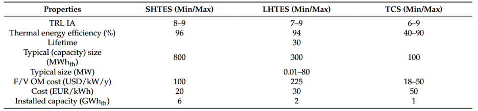
Existen tres categorías de tecnología de almacenamiento – calor sensible, calor latente y almacenamiento termoquímico. Las características más fundamentales de estas tecnologías están resumidas en la tabla a continuación. Las tecnologías de calor sensible utilizan la capacidad de materiales como agua, sales fundidas o hormigón de absorber calor cuando se calientan. En el caso del calor latente, se aprovecha la gran capacidad de algunos materiales de absorber calor durante un cambio de fase. Por último, las tecnologías termoquímicas emplean reacciones químicas reversibles; cuando el sistema se carga, el calor disponible activa una reacción que lo consume. Durante un descargue, la reacción se invierte y libera el calor.

Tabla 1: Características de diferentes tecnologías de almacenamiento. SH-TES – almacenamiento de calor sensible. LH-TES – almacenamiento de calor latente. TCS – almacenamiento termoquímico. Fuente.

De las tres familias de tecnologías, la de almacenamiento por calor sensible es la más desarrollada y exhibe los costes más bajos (ver Tabla 1). Esto se debe a su relativa simplicidad – el sistema es diseñado para albergar un solo material en la misma fase. Los sistemas termoquímicos aún se encuentran en fase de desarrollo, mientras que los sistemas de calor latente ya se utilizan ampliamente a bajas temperaturas en aplicaciones civiles e industriales, pero requieren más pruebas para temperaturas más altas (por encima de 250ºC). Ambas pueden abordar el gran tamaño físico de los sistemas de calor sensible, una de sus principales desventajas, que se debe a la relativamente baja densidad térmica de los materiales usados (mostrada en la tercera columna de la tabla de arriba).

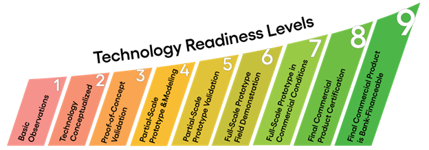
Ilustración 1: Una escala de utilizada para evaluar la madurez de una tecnología, desde la investigación básica (nivel 1) hasta la comercialización (nivel 9). Fuente

En una publicación de 2023 en la revista científica “Processes”, los autores predicen el futuro próximo del almacenamiento térmico. Según ellos, hasta el fin de la década el almacenamiento termoquímico alcanzará el nivel de desarrollo tecnológico entre 6 y 9 (Tabla 2), que corresponde al menos a una demostración de campo (Ilustración 1). Esto es un gran avance desde los niveles de entre 3 y 5 reportados en el momento de publicación. De manera similar, se esperan avances que llevarán los sistemas de calor latente desde los niveles entre 4 y 7 en el inicio de la década hasta niveles entre 7 y 9 en 2030. Como hemos dicho, las tecnologías de calor sensible ya están bastante desarrolladas (niveles 7-9), pero se esperan avances incrementales hasta niveles 8-9 en los próximos años. La mayoría de los esfuerzos en este ámbito están en el uso de nuevos materiales a la vez de las típicas sales fundidas, agua bajo presión o aceite térmico.

Para todas las familias de tecnologías se espera una subida de la capacidad instalada acumulada y con esto un crecimiento de los tamaños típicos de las unidades y sus eficiencias térmicas. Todo esto es propicio para generar economías de escala, que bajan los costes de los proyectos. El ritmo de instalación en las industrias entonces será clave para desanclar el potencial de las tecnologías.

Tabla 2: Proyecciones de desarrollo hasta 2030. Fuente.

Más allá de los avances técnicos y económicos, también resulta crucial considerar el impacto ambiental de estas tecnologías de almacenamiento térmico, aspecto que se analiza en la siguiente sección.

¿Contamina el almacenamiento térmico?

En esta sección vamos a enfocarnos en el impacto ambiental de la sal solar gracias a la publicación con acceso abierto de Lambrecht et al. Esta sal es uno de los medios más típicos usados en los sistemas de almacenamiento sensible en las plantas termosolares y esto facilita su adopción para el almacenamiento térmico industrial. Está compuesta por un 40 % de nitrato de potasio (KNO₃) y un 60 % de nitrato de sodio (NaNO₃) y este último material representa el mayor factor de impacto en todas las categorías analizadas.

Los principales efectos ambientales a lo largo del ciclo de vida de esta sal térmica se concentran en la salud humana (por toxicidad), los ecosistemas acuáticos (eutrofización y ecotoxicidad del agua) y el medio edáfico (transformación del suelo). A pesar de estos impactos ambientales (y no debemos olvidar que nada tiene un impacto nulo) la sal solar presenta un perfil ambiental notablemente más favorable que el del aceite térmico Therminol que también se usa en sistemas de almacenamiento sensible, siendo entre ocho y nueve veces menos dañina. También existen otras sales con propiedades similares que utilizan menos NaNO₃ y gracias a esto mejoran ligeramente su perfil ambiental cara a cara la sal solar estándar.

Sin embargo, otros materiales pueden tener impacto aún más bajo. Se están invirtiendo considerables esfuerzos de investigación para impulsar la economía circular en el ámbito del almacenamiento térmico. Por ejemplo, el proyecto de Horizon FLUWS tiene el objetivo de desarrollar un sistema que usa desechos de la industria cerámica como medio de almacenamiento hasta el nivel de madurez tecnológica de 5. Otro enfoque científico es el uso de residuos de construcción y demolición e y así aprovechar este flujo masivo de desechos industriales con bajo coste.

El mundo de la energía lleva años cambiando y el sistema nuevo y mejorado ya ha tomado forma. El sector industrial forma parte de ello y en nuestra próxima publicación profundizaremos con algunos ejemplos reales; en poco tiempo tú fábrica podría formar parte de esta misma lista. En FersiSolar S.L. somos expertos en almacenamiento y energía solar concentrada para industrias y empresas. Si estás buscando soluciones para formar parte del futuro y descarbonizar tu proceso, contáctanos, el mundo no puede esperar.

Nighttime solar electricity: Hybrid CSP plants with thermal storage

Cover image: Redstone power plant in South Africa. Source

How can we make solar power at night? Solar PV is extremely successful at generating solar power during daytime. However, once the sun sets the grid needs to rely on more expensive nuclear, geographically limited hydro or polluting gas and coal. If we want to use solar power during the night, concentrated solar (CSP) is probably the most competitive solution. Making hybrid PV-CSP and PV-wind-CSP plants to tap into the strengths of the different renewable technologies might be the best way to have cheap, low-carbon electricity 24 hours per day.

Thermal energy storage with molten salts – the key to 24/7 solar production

Why is CSP better than PV for providing power at night? It is that the two solar technologies have different outputs. While PV panels provide us with electric current directly, CSP creates heat – steam that needs to run through a turbine to generate electricity. The ace up CSP’s sleeve is that thermal energy can be stored much more easily than electric energy.

Most thermal storage technologies use the sensible heat of a fluid – usually molten salt. The salt heated from the solar field is stored in the hot tank, where it remains at up to 550ºC until the electricity prices become attractive enough for the plant to start producing. Once the salt leaves the hot tank, its energy is passed to the water that circulates in the power block through a heat exchanger. With its temperature now low, the salt is sent to the cold tank. There, it is kept above its freezing point (well above 100ºC) to ensure it doesn’t solidify before the next production cycle begins. This is a rather efficient roundtrip, with up to 99% of the produced energy arriving at the power block.

Figure 1: Schematic of a molten salt storage system with two tanks. Source link.

Compared to batteries (BESS), thermal storage (TES) using molten salts can offer lower costs and avoids issues surrounding batteries’ toxicity and flammability. From an environmental point of view, molten salt TES can offer rather low impacts in a wide range of categories, including acidification, marine and human toxicity and embodied greenhouse gas emissions.

Another advantage that molten salt TES has over battery systems is its lifespan. BESS, for example lithium-ion, typically last 10 to 15 years, with performance degrading after a number of cycles due to chemical aging and thermal stress. In contrast, TES systems using molten salts can last up to 30 years with minimal degradation, as they rely on simple heat transfer rather than electrochemical reactions.

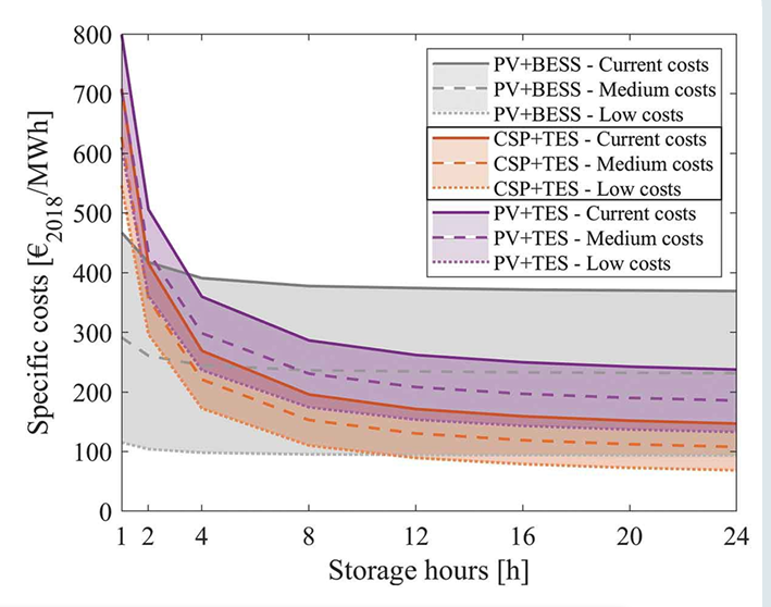
The lower price tag holds true, especially when considering a larger system that could offer sustained output over multiple hours, as shown by a study by the TU Wien below. Although battery energy storage systems have enormous potential for cost reductions, it is highly unlikely that a battery system designed to store electricity for more than 2-3 hours will ever be cheaper than its molten salt counterpart. Thus, even though BESS are absolutely essential for the future grid and should be installed at massive scale, there are niches in which TES outperforms them.

Another important takeaway from the same study is that it is unlikely that PV-TES systems (using some form of heaters as an intermediary) will become more economical than CSP-TES. This ensures the future of CSP itself as part of the energy transition.

Figure 2: Specific costs of different combinations of technologies. BESS – battery energy storage system. TES – thermal energy storage. CSP – concentrated solar power. PV – photovoltaics. Source link

Hybrid renewable plants with storage – closing the gap in energy production

The promising way forward then seems to be to design hybrid plants, where PV panels with some BESS take care of electricity supply during the day, while CSP with TES keeps the lights on during the night. Clearly, CSP can be integrated with wind energy too, not only with PV. In that case, rather than strictly operating at night, the CSP can focus on moments with low winds.

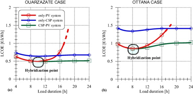
According to a study by researchers from the University of Calgary, if a solar-only plant wants to sustain a continuous load for more than 8-9 hours, the hybridization of concentrated solar power with thermal energy storage (CSP-TES) and photovoltaics with battery storage (PV-BESS) systems offers significant financial benefits. According to their results (see graph below), a hybridized plant designed to run uninterruptedly for 24 hours could have a lower levelized cost of electricity compared to a PV-BESS plant designed to provide 4 hours of service per day.

Figure 3: Levelized cost of electricity of different plant configurations at locations in Morrocco (Ouarzazate) and Italy (Ottana). Source link

The Chinese government has understood this. In the last year of 2024 alone, three projects with 250 MW of CSP were commissioned, all of them hybrid plants, combining CSP with PV and onshore wind (see page 27 here). All projects featured at least 8 hours of thermal storage, allowing for nighttime operation and peak shaving. And there are more projects on the way, 3.3 GW of CSP is under construction, with most of these projects expected to be completed in 2025 (page 28 here).

It is important to stress that these hybrid projects are significantly bigger than only their CSP part, because CSP and PV are not competing with one another, but working together. For example, the capacity of the projects finished last year sits just above 1.5 GW, six times larger than the CSP components alone. The fact that CSP plants are more expensive and require more maintenance than their photovoltaic cousins, gives them a specialized, but absolutely crucial role in the toolbox of the future renewable energy mix.

At FersiSolar S.L. we are experts at CSP, Storage, Concentrated Solar Heat for industries and businesses. If you want a 24/7 clean energy solution, contact us. The world cannot wait…

Or maybe you know any other ways to address this frontier of renewable energy??

Solar energy for industrial processes

Solar energy for industrial processes

Or how to reduce CO2 emissions in industry

The decarbonization of industrial heat is an important challenge on the path toward reducing emissions in industry. 32% of global energy consumption is used in industry, and 74% of this energy consumption is used for heat production, according to the International Energy Agency (IEA). Two-thirds of this heat is used to supply processes at temperatures above 150°C, such as distillation, dyeing, bleaching, or material transformation processes. The Orennia chart above shows a more detailed breakdown of consumption across different sectors, together with their contribution to greenhouse gas emissions.

Concentrated solar power (CSP) is perfectly positioned to supply heat up to 500°C. This makes CSP for industrial heat particularly relevant for industries that account for up to 15% of global CO2 emissions, such as:

  1. Plastics and chemicals
  2. Paper
  3. Food processing
  4. Textiles

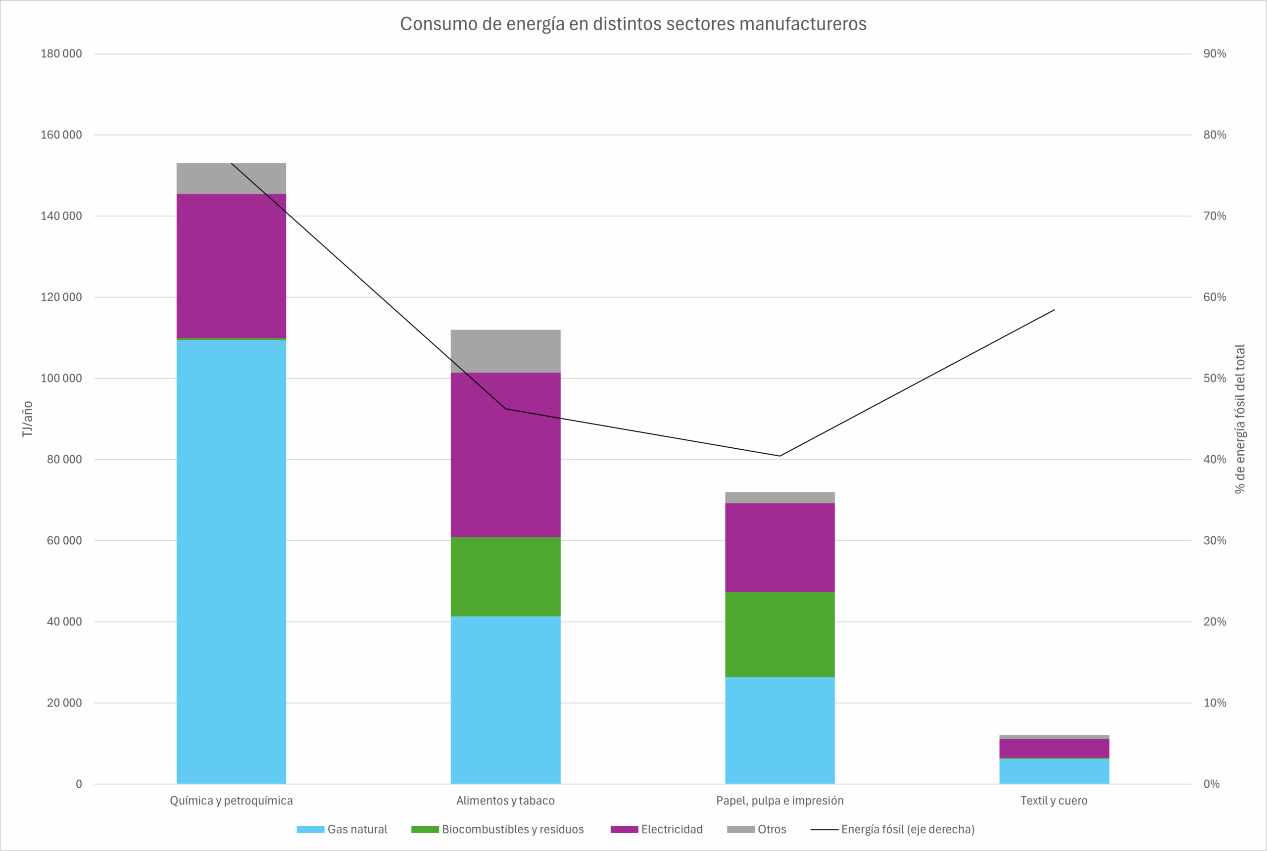
In Spain, clean technologies for industrial processes play an important role in these sectors through electricity consumption and the use of biomass to supply heat. However, fossil fuels (mostly natural gas, together with small amounts of coal and petroleum products) provided between 40% and 76% of energy in 2021, according to the IEA chart below. This opens the door to a strong expansion of solar energy in industry and the use of CSP in factories in the coming years.

At FersiSolar S.L., our advanced technology can supply heat up to 500°C, contributing significantly to CSP for industrial decarbonization. The use of storage systems will be essential for solar energy to exceed 50% of the annual heat supply. In this area, we have storage technologies using water tanks, molten salts, or thermal oils, as well as concrete heat storage systems.

CSP brings many benefits to industry. It would not only reduce CO2 emissions but also increase energy savings in industry through greater energy efficiency in these industrial processes. A sustainable and reliable supply of locally produced heat would reduce dependence on natural gas imports from abroad and exposure to price shocks. The latter is especially important for industrial profitability, something we were reminded of again in 2022 with the Russian invasion of Ukraine and the crisis it triggered.

By integrating CSP, concentrated solar energy for industrial processes can contribute to a cleaner and more sustainable future for industrial processes. Let us know your heat requirements; we have a solution.