Solar heat for the minerals industry

The production of gypsum requires a constant heat supply to ensure product quality and process efficiency. Concentrated solar thermal energy with thermal energy storage offers an alternative to gas for industrial processes in the minerals sector. With this technology, it is possible to generate hot air and reach temperatures of up to 400°C, achieving 78 percent thermal coverage or more at the plant.
In addition to providing renewable heat for the minerals industry, a concentrated solar system can help avoid energy volatility in industry, as it provides predictable costs with solar energy and a low levelized cost of heat (LCOH). This makes competitive solar heat for factories a viable option for reducing emissions of greenhouse gases and pollutants and improving the sustainability of production.
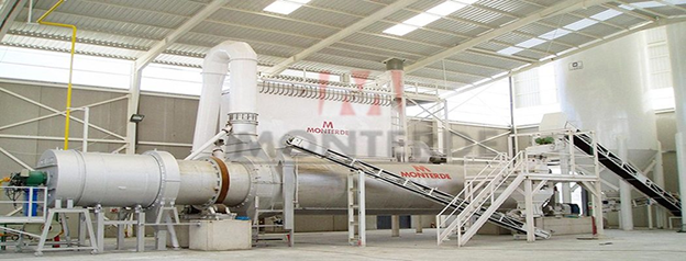
Figure 1: Example of a rotary kiln
And how do we decarbonize gypsum production in practice? First, we have to dry gypsum rock, a sedimentary rock composed of calcium sulfate and water. In this specific case, we need hot air at 300°C and a rotary kiln (Figure 1) to obtain different materials used in construction.
Heat generation
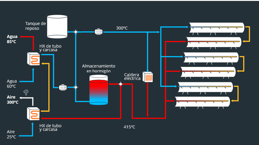
Figure 2: System schematic
As always, we start with heat generation (Figure 2), and for this we use parabolic trough collectors (PTCs). We have already discussed how they work in a previous article (here), so we will not go over the basics again. Unlike the previous cases described, in this project we need to supply heat at temperatures above 250°C, the practical limit of pressurized water as a working fluid. To reach this temperature, we use thermal oil designed to operate at up to 425°C. This silicone-based product has a higher boiling point than water—380°C at atmospheric pressure. We still need to keep the system under pressure for safety reasons, but at pressures below the 40 bar used in the water system.
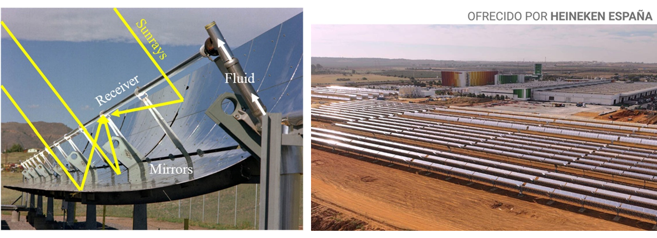
Figure 3: Parabolic trough collectors
Since this project operates at very high temperatures, it is essential to insulate the collector properly to prevent energy losses. The solar collector receiver is a tube onto which the solar rays are focused. As the working fluid passes through this tube, its temperature rises. If the tube is in contact with the atmosphere, some of the concentrated heat escapes through convection; the loss is proportional to the difference between the temperature of the tube and the ambient air.
In projects where the tube and fluid reach temperatures of 150–170°C, the tube can be insulated by placing it inside another transparent tube filled with a noble gas such as argon. However, at temperatures above 200°C, argon cannot provide sufficient insulation, and vacuum insulation technology is required. In Figure 4, the metal tube containing the working fluid is shown in purple; this tube is housed inside another glass tube, with an insulating vacuum between them. This type of receiver is more expensive and less reliable than receivers without insulation, but its use is essential to prevent prohibitive heat losses.
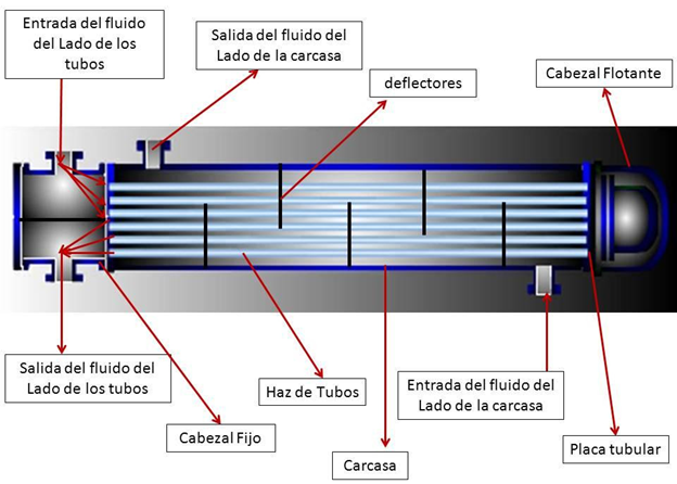
Figure 4: Schematic of a vacuum-insulated absorber tube
Storage system
Once the heat has been generated, it must be stored until it is needed. Thanks to the concrete thermal energy storage system (TES), it is possible to ensure 24/7 operation and process continuity, even when there is no sunlight. In this case, the thermal battery can supply all the heat required by the kiln for up to 12 hours without needing to be recharged. Due to the high temperatures of the stored heat, the TES is made of concrete. In basic terms, we have a concrete block with integrated pipes (Figure 5). During charging, the working fluid from the solar field flows through these pipes, heating the block. During discharge, the cold fluid enters through the same pipes and is heated by absorbing heat from the block.
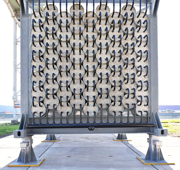
Figure 5: The ThermalBattery from EnergyNest
Unlike a water TES, concrete has lower convection losses; in addition, the system is simple, robust, and economical. However, the concrete formulation must be optimized to achieve the desired properties and maximize performance. Two parameters are key:
- Thermal conductivity: the higher it is, the faster the TES charges and discharges. It can be improved by modifying the type and particle-size distribution of the aggregates, adjusting the proportions of the concrete components, or adding additives such as conductive fillers or fibers.
- Specific heat capacity: the higher it is, the more energy can be stored per unit of mass. It can also be optimized by changing the type and grading of the aggregates and the composition of the mixture.
In addition to their low cost, concrete TES systems eliminate the risk of leaks compared with tanks containing liquids such as water or molten salts. Their main disadvantage is that, because concrete is a solid, a minimum temperature difference of 25–30°C between the temperature of the flowing fluid and the concrete is required to achieve adequate heat exchange. This temperature difference is present during both charging and discharging, which means that the fluid received by the customer has a temperature at least 50°C lower than the fluid leaving the solar field.
Energy supply, standby, and conclusion
To supply heat to the customer, we use two shell-and-tube heat exchangers, equipment that we have already described previously (here). The first operates at a higher temperature and heats the air used in the kiln to 300°C. After leaving this heat exchanger, the thermal oil enters the second unit to heat water to 80°C. This water is used for other industrial processes, provides sanitary hot water for workers, and, during winter, is used to heat the factory buildings. Once all the energy has been extracted from the thermal oil, it is stored in a tank until its next circulation through the solar field. This tank serves a second purpose: it is sized so that it is never completely full, allowing it to accommodate the expansion of the thermal oil that occurs when it is heated.
Thanks to this heat storage and distribution configuration, the system ensures a continuous and efficient thermal supply for all the customer’s processes. With it, we have achieved a solar coverage of 78% of thermal demand, placing our customers at the forefront of decarbonization, both in the minerals industry and across the raw materials sector.
At FersiSolar, we know how to design, build, and operate such plants and help you decarbonize your industrial heat consumption. The time to act on climate change is now, and the solution already exists. Contact us.


